
2026 Top Optical Attenuator Types for Global Buyers
Global fiber networks now demand tighter control over optical power, especially in data centers, telecom rooms, and testing laboratories. An Optical Attenuator helps reduce excessive signal strength without interrupting the transmission path. That small function can protect receivers, improve measurement accuracy, and stabilize sensitive equipment.
This guide examines the main Optical Attenuator types available to global buyers in 2026. It covers fixed attenuators, variable attenuators, inline models, plug-in designs, bulkhead units, and variable optical attenuators. Each type serves a different installation condition. A fixed model may suit a stable link, while a variable model offers adjustment during commissioning or testing. Connector format, wavelength range, return loss, insertion loss, and attenuation accuracy also require careful review.
Details matter here.
From practical fiber inspections, connector cleanliness often affects results more than buyers expect. A dusty interface can create unstable readings and misleading performance data. Reliable suppliers should provide test records, clear specifications, traceable quality procedures, and compatibility guidance. International buyers should also confirm connector polish, fiber mode, operating temperature, and regional purchasing requirements before placing an order.
No selection guide is flawless. Field conditions can expose weaknesses that laboratory charts hide. A low-cost attenuator may appear attractive, yet poor calibration or weak housing can increase maintenance costs. This article therefore compares technical performance with installation practicality, supplier reliability, and long-term value. The goal is not to promote one universal solution. It is to help engineers, distributors, and procurement teams make better-informed decisions across different network environments.
What Optical Attenuators Are and Why Global Buyers Need Them
What Optical Attenuators Are and Why Global Buyers Need Them
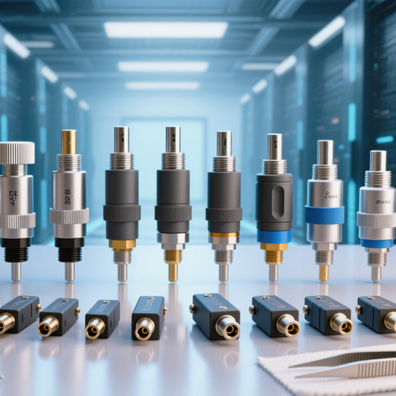
Optical attenuators are passive devices that reduce excessive light power in fiber networks. They protect receivers from overload and stabilize signal measurements. Common types include fixed, variable, plug-style, and inline attenuators. Fixed units suit predictable links, while variable units support commissioning and laboratory testing. In field installations, the required value depends on distance, connectors, splices, wavelength, and receiver sensitivity. A small 3 dB error can matter.
Demand is becoming less forgiving. The OECD Broadband Statistics report placed fiber at about 42% of fixed broadband connections across OECD economies in June 2024. TeleGeography’s 2024 Global Bandwidth Research Service also reported strong international bandwidth growth, near 29% during 2023. More fiber traffic means tighter power-budget control. Attenuators help prevent receiver saturation without replacing expensive network equipment. Buyers should verify insertion loss, return loss, connector polish, operating wavelength, and calibration records. IEC 61300-3-4 provides recognized measurement guidance for attenuation testing.
Real installations are messier. Dust, temperature changes, and mismatched connectors can shift results. A spreadsheet can still mislead. I recommend testing the complete link, not only the attenuator package. Engineers should also leave practical margin between calculated power and receiver limits. The perfect attenuation value rarely exists on the first attempt. Supplier documentation, traceable test data, and compatibility checks are more reliable than a low unit price.
2026 Top Optical Attenuator Types for Global Buyers - What Optical Attenuators Are and Why Global Buyers Need Them
| Optical Attenuator Type | How It Works | Typical Attenuation Range | Common Wavelength Windows | Typical Applications | Key Advantages | Important Buyer Considerations |
|---|---|---|---|---|---|---|
| Fixed Optical Attenuator | Uses a permanent absorbing, reflective, or gap-based optical element to reduce signal power by a preset amount. | Commonly 1–30 dB; higher values are available in specialized designs. | 850 nm, 1310 nm, 1550 nm, and other specified bands. | Fiber-optic links, receiver protection, laboratory references, and power equalization. | Simple, compact, passive, reliable, and usually cost-effective. | Confirm attenuation tolerance, connector type, return loss, power rating, and wavelength compatibility. |
| Inline Fiber Attenuator | Attenuation is integrated into a short fiber assembly installed directly between two optical connections. | Typically 1–20 dB, depending on the assembly and operating wavelength. | Most commonly 1310 nm and 1550 nm; multimode versions may support 850 nm. | Existing patching systems, field retrofits, access networks, and equipment interconnection. | Fast installation without changing equipment or adding a separate adapter body. | Check fiber mode, cable construction, connector polish, insertion loss, bend radius, and environmental protection. |
| Plug-Type or Adapter Attenuator | A connectorized attenuating element is fitted between a transceiver port and a mating fiber connector. | Commonly 1–15 dB, with other preset values available. | Usually 1310 nm and 1550 nm for single-mode systems; 850 nm for selected multimode systems. | Data-center links, telecom equipment, test benches, and quick network balancing. | Easy to deploy, removable, and suitable for correcting excessive received optical power. | Verify connector gender, keying, polish type, port clearance, mechanical durability, and accidental-disconnection risk. |
| Variable Optical Attenuator (VOA) | Allows attenuation to be adjusted manually or electronically, enabling controlled optical-power changes. | Often 0–20 dB or 0–30 dB; some laboratory and network modules provide wider ranges. | Commonly 1310 nm, 1550 nm, and extended-band telecom wavelengths. | Optical testing, automatic power control, receiver sensitivity testing, and network commissioning. | Flexible power adjustment and repeatable control for changing test or network conditions. | Evaluate adjustment resolution, calibration stability, response time, control interface, drive requirements, and operating temperature. |
| MEMS-Based Attenuator | A micro-electromechanical structure changes the optical path or coupling between fibers to control transmitted power. | Commonly adjustable up to approximately 30 dB; exact range depends on the design. | Primarily 1310 nm and 1550 nm telecom bands. | Optical switching platforms, test instruments, monitoring systems, and automated network equipment. | Compact size, electronic control, repeatability, and suitability for high-density modules. | Check switching or adjustment speed, drive voltage, long-term repeatability, optical power handling, and control protocol. |
| Motorized Variable Attenuator | A motor moves an optical filter, wheel, shutter, or alignment mechanism to provide programmable attenuation. | Often 0–60 dB in laboratory-oriented equipment, depending on configuration. | Available for visible, 850 nm, 1310 nm, 1550 nm, and other specified ranges. | Automated measurement systems, production test stations, calibration setups, and research laboratories. | Wide adjustment range and computer-controlled operation. | Consider adjustment speed, mechanical wear, positioning accuracy, noise, interface compatibility, and calibration requirements. |
| Liquid-Crystal Variable Attenuator | An electrically controlled liquid-crystal cell changes polarization or transmission to regulate optical power. | Commonly adjustable over approximately 20–40 dB, depending on wavelength and optical design. | Usually designed for a defined wavelength band rather than all wavelengths simultaneously. | Optical instruments, imaging systems, research equipment, and precision power control. | No mechanical motion, fine electronic control, and low vibration. | Check polarization sensitivity, wavelength range, response time, temperature behavior, residual transmission, and drive electronics. |
| Dual-Window or Broadband Attenuator | Uses an optical design intended to maintain specified attenuation across two windows or a relatively broad wavelength band. | Common preset values include 3, 5, 10, 15, and 20 dB; exact tolerance varies by wavelength. | May cover 1310/1550 nm dual windows or a wider defined operating band. | Multi-wavelength networks, optical testing, wavelength-division systems, and upgrade projects. | Reduces the need to stock separate attenuators for each supported wavelength window. | Review attenuation flatness, wavelength-dependent tolerance, return loss, connector standards, and compatibility with the optical link budget. |