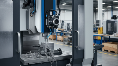
What Are CNC Turning Parts and How Are They Made?
CNC turning parts are components shaped by rotating bar stock against a cutting tool. The process is common in automotive, medical-device, and industrial equipment production. Think of a steel shaft emerging with a smooth journal, a narrow groove, and crisp threads. Those features are cut on a lathe, often in one carefully planned sequence. Small choices matter.
A turning cycle starts with a drawing and material selection. The bar is secured in a chuck, then rotated while the tool removes material. Operators set speeds, feeds, and tool paths to suit the alloy and required finish. A CNC program controls these movements, but the machine does not guarantee a perfect result. Tool wear, workholding, and measurement all affect the finished part. Shop-floor checks remain essential.
For transparency, the following line is an illustrative quotation from a fictional composite specialist, not a verified statement by a real expert: “A reliable turned part begins with a stable setup and ends with a measured result.” That distinction matters when evaluating manufacturing advice. This guide explains what cnc turning parts are, how turning operations shape them, and which design and inspection details influence cost and consistency. You will also see where the process has limits. A thin wall can chatter. A tight tolerance may need extra inspection. Real production is rarely as neat as a diagram suggests.
What Defines a CNC-Turned Part
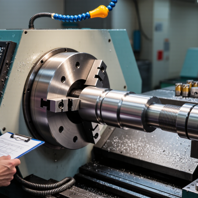
A CNC-turned part is a component shaped mainly by rotating a workpiece against a cutting tool. Its defining feature is geometry organized around an axis, such as a shaft, sleeve, pin, or threaded fitting. The machine controls tool movement to form diameters, shoulders, grooves, and end faces. The workpiece may be metal or plastic, depending on the part’s load, environment, and design requirements.
That matters. A component does not qualify simply because it looks round. Its drawing specifies details such as diameter, length, concentricity, thread form, and surface finish. For example, a bearing seat may need a close diameter tolerance so the bearing fits securely without excessive force. A machinist checks critical features with tools such as micrometers and gauges. Small details count. Some parts also include flats or cross-holes, often produced with additional machine operations. The boundary can get messy: a drawing may combine turned and milled features, so the manufacturing plan should identify which surfaces are created by turning. A clear definition helps connect the part’s function to practical inspection and production choices.
How a CNC Lathe Shapes Rotating Workpieces
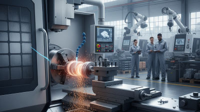
A CNC turning part starts as a bar or blank held firmly in a lathe chuck. The spindle rotates the workpiece, while a cutting tool moves along controlled paths. This action can reduce the outside diameter, create shoulders, or cut grooves. A boring tool can also shape an internal hole. The machine follows programmed coordinates, but the setup still matters. Incorrect tool offsets or weak clamping can leave uneven surfaces or parts out of tolerance.
Tips: Check the drawing before machining. Confirm stock size, tool position, and chuck grip. Watch for vibration; a faint rhythmic chatter can signal trouble. Measure the first part with suitable gauges before running a full batch.
Turning is not just spinning metal and removing material. Cutting speed, feed rate, tool geometry, and material hardness all affect heat and finish. Coolant may help control temperature and clear chips, though it is not a cure for every problem. In practice, the first setup may need adjustment. A smooth surface can still hide a diameter error, so inspect critical features during production. Small details matter.
Materials and Designs Suited to CNC Turning
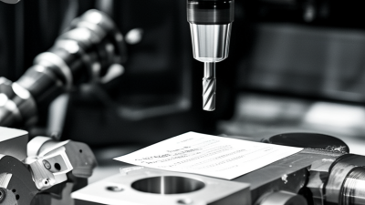
CNC turning parts are made by rotating bar stock while a cutting tool removes material. The process naturally suits shafts, pins, bushings, rollers, and threaded fittings with round or stepped profiles. A turned surface may show fine circular tool marks, especially under angled light. Those marks are normal, but the required finish should match the part’s function.
Material choice affects cutting behavior, strength, weight, and finish. Aluminum is light and machines readily, making it useful for housings and spacers. Brass often produces clean details in small fittings. Steel and stainless steel suit parts needing strength or corrosion resistance, though grades differ in machinability. Titanium can reduce weight while retaining strength, but it may require careful heat and tool management. Designs with bores, shoulders, grooves, and external threads are usually practical. Very thin walls or deep, narrow features can deflect, vibrate, or wear tools faster. A tighter tolerance is not automatically better; it can add cost without improving performance.
Tips: Specify only functional tolerances, and include a clear datum. Check that tools can reach internal features. Keep the first design simple. It may still need revision after a prototype reveals burrs, fit issues, or an unexpectedly rough surface.
Typical Densities of Materials Used for CNC Turning
Material choice affects a turned part’s weight and machining behavior. These approximate room-temperature densities vary by alloy and grade. CNC turning is well suited to rotational designs such as shafts, bushings, pins, and threaded components.
How CNC-Turned Parts Are Made from Design to Machining
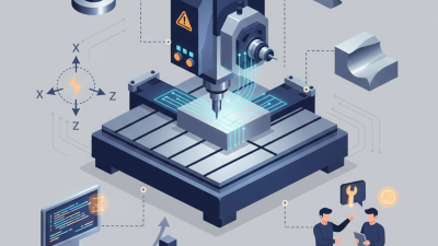
CNC turning starts with a drawing that defines dimensions, tolerances, surface finish, and material. The designer then checks whether the part can be held securely and machined without tool collisions. A cylindrical bar is clamped in a chuck and rotated while cutting tools shape its outside diameter, face, grooves, or threads. Small details matter: a deep, narrow groove may need a special tool and extra machining time. The process plan sets the tool sequence, spindle speed, feed rate, and coolant use. CAM software converts the design into machine instructions, which an operator reviews before cutting. The first part is measured with tools such as micrometers or gauges. Adjustments may follow. That step can feel repetitive, but it catches errors before a full batch is made.
Digital records can help connect design, machine settings, and inspection results. Deloitte and MAPI’s 2024 Smart Manufacturing Survey, based on 600 manufacturing executives, found that 92% expected smart manufacturing to drive competitiveness within three years. This supports investment in process data, though it does not guarantee a precise part. Material variation, tool wear, and setup choices still affect results.
Tips: Keep critical dimensions and tolerances clear on the drawing. Ask the machinist to review thin walls, tight internal corners, and long overhangs before production. A small design change may simplify machining, but it can also affect fit. Check the first piece against the drawing before approving the batch.
How Turned Parts Are Finished and Inspected
After turning, a part may still carry a thin burr around its edge. A machinist removes it with a fine file, abrasive pad, or controlled deburring tool. Edges may also be chamfered to ease assembly. Small marks matter. Polishing can improve appearance and reduce roughness, but it can also remove material. A bright surface alone does not prove that a part meets its drawing.
Inspection checks the features that affect fit and function. Micrometers measure shaft diameters; bore gauges check internal features. Thread gauges verify threaded sections, while a roundness tester can reveal lobing that a diameter check misses. Surface texture is commonly measured as Ra, the arithmetic mean deviation of a surface profile. ASME B46.1 defines surface-texture parameters, but the required Ra value must come from the part specification.
Measurement results need context. NIST Technical Note 1297 explains how to report measurement uncertainty and describes a coverage factor of k = 2, which often corresponds to roughly 95% coverage under appropriate assumptions. That matters when a measured diameter sits close to its tolerance limit. A shop should use calibrated instruments, record results, and keep the part supported consistently. Inspection is not perfect; even careful handling can affect a delicate finish.