Top 10 Types of Milling Machine Parts for Buyers

Choosing milling machine parts is not just a matter of comparing prices. The right components affect accuracy, uptime, and the finish on every workpiece. A worn spindle, loose lead screw, or poorly matched cutter can turn a routine job into hours of adjustment.

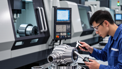
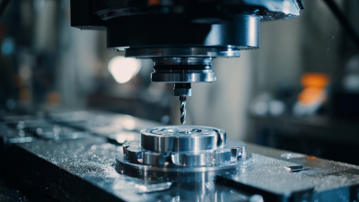
This guide introduces ten common milling machine parts buyers should understand before placing an order. It covers core components such as the spindle, table, column, milling head, and feed mechanism, along with cutters and other frequently replaced items. Each part serves a different purpose. Some influence machine rigidity; others guide movement or remove material. Small details matter.

For buyers, the part name alone is not enough. Check the machine model, dimensions, mounting style, material, and expected operating load. Ask for drawings or specifications when compatibility is unclear, and confirm how the supplier verifies quality. A component that looks suitable in a product photo may not fit your machine. That is easy to overlook.

Actual needs vary by machine type, workload, and maintenance history. This overview offers a practical starting point, not a substitute for checking manufacturer documentation or consulting a qualified technician. Even experienced buyers sometimes miss a small fitment detail. A careful review of these ten milling machine parts can help narrow choices, reduce avoidable downtime, and support more informed purchasing decisions.
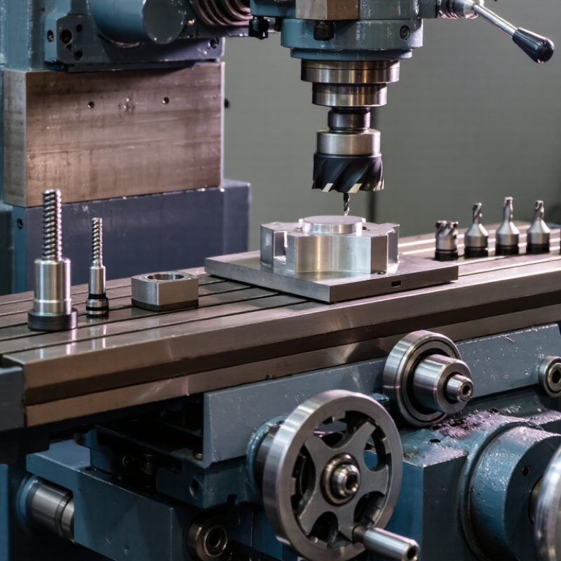
Top 10 Types of Milling Machine Parts for Buyers

Understanding the Main Systems of a Milling Machine

Understanding the Main Systems of a Milling Machine

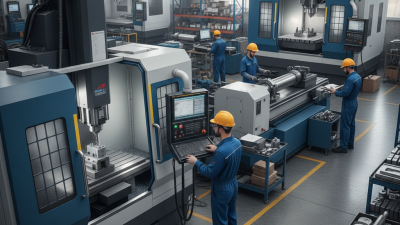
A milling machine works through several connected systems, not just a rotating cutter. The base supports the machine and helps absorb vibration. Above it, the column carries the knee, saddle, and table. These parts move the workpiece along controlled axes. The spindle holds and rotates the cutting tool, while the head or ram positions it over the work. Small parts matter. A loose feed handle or worn gib can affect accuracy, even when the machine looks sound.

The drive and feed systems control speed and movement. Manual machines use handwheels, while powered models may offer automatic feeds or digital controls. Coolant helps manage heat and clear chips, and lubrication protects sliding surfaces. Buyers should check for smooth table travel, steady spindle operation, and unusual noise. Inspect the ways for scoring and look for backlash at the handwheels. A clean appearance can be reassuring, but paint alone tells little about wear. It is easy to focus on the spindle and overlook the feed mechanism.

Tips: Move each axis through its full travel and feel for tight spots. Ask how the machine was maintained, then verify visible wear yourself. If possible, test it under light cutting load. A brief test is useful, though it cannot reveal every issue. Keep the intended work, available floor space, and service access in mind when comparing machine types.

How Milling Machine Parts Work Together

A milling machine works as a connected system, not a collection of independent parts. The base supports the machine and absorbs cutting forces. The column rises from it, holding key drive components in position. The knee moves vertically, while the saddle and table provide crosswise and lengthwise travel. Rigid support matters. If these parts flex, a cutter may leave chatter marks or an uneven surface.

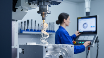
The spindle turns the cutting tool at a controlled speed. On some machines, an arbor supports the cutter; on others, the tool fits directly into the spindle. Feed screws and handwheels move the table, while powered feeds can maintain steadier motion during longer cuts. These movements must stay coordinated with spindle speed and cutter choice. Coolant may reduce heat and carry chips away, but it cannot correct poor alignment or a dull tool.

For buyers, inspect how smoothly the table travels across its full range. Watch for backlash, rough spots, loose handles, and unusual spindle noise. A small amount of movement may be normal, depending on machine design and condition. Still, “it runs” is not the same as accurate operation. Even a clean-looking machine can hide worn bearings or uneven ways, so a practical test cut offers useful evidence.

The Top 10 Types of Milling Machine Parts

A milling machine depends on ten core parts working together: the base, column, knee, saddle, worktable, spindle, arbor, overarm, ram, and feed mechanism. The base anchors the machine and absorbs vibration. The column supports the knee and houses key drive components. On many machines, the knee moves vertically, while the saddle carries the table across it. Small alignment errors can show up as uneven cuts.

The worktable clamps the job in place, so inspect its T-slots for burrs and damage. The spindle rotates the cutting tool; the arbor supports cutters on machines designed for arbor mounting. The overarm and ram provide support or reach, depending on machine design. Feed mechanisms control table movement. Their backlash matters. These arrangements vary, and the ten-part list is not universal.

Buyers should match each part to the machine’s layout, travel, load, and maintenance needs. Grand View Research valued the global CNC machine market at USD 83.99 billion in 2023. Its report projected 9.3% annual growth from 2024 through 2030. That market context makes precision components relevant, but it does not prove every buyer needs the same configuration. Check drawings, tolerances, and replacement-part compatibility before ordering. A detail is easy to miss.

Key Specifications Buyers Should Compare

Compare each part against the job’s load, accuracy, and duty cycle. For spindle assemblies, check taper type, maximum speed, bearing arrangement, and allowable runout. A spindle rated at 8,000 rpm may not suit continuous high-speed cutting. Ask how runout was measured, and at which speed. Small details matter.

For ball screws and linear guideways, compare axis travel, positioning accuracy, repeatability, preload, and protection against chips and coolant. ISO 230-2:2014 specifies methods for testing machine-tool axis positioning accuracy and repeatability. Request the test results, not just a catalog tolerance. One catch: results depend on test conditions. Compare like with like, including temperature and measurement length. Check whether the stated value covers one axis or the whole machine.

For motors and drive units, review rated power, torque across the speed range, cooling needs, and duty cycle. The U.S. Department of Energy’s 2014 Motor Systems Market Assessment reports that motor-driven systems use about 54% of electricity in U.S. manufacturing. That figure covers manufacturing broadly, not milling machines alone, but it makes drive efficiency worth checking. Also compare rated load against your actual cutting schedule. A low purchase price can hide costly maintenance. Ask for replacement intervals and parts availability; these are easy to overlook.

How to Choose Parts for Your Machine and Workload

Choosing among milling-machine parts starts with the workload, not the catalog. Match spindle bearings, tool holders, cutters, table ways, and feed screws to material, cut depth, and duty cycle. Heavy steel cuts need rigidity and heat control; repeated aluminum jobs may need higher spindle speeds and effective chip clearing. The U.S. Department of Energy’s motor-systems sourcebook estimates that motor-driven systems use 69% of U.S. industrial electricity. It also reports potential energy savings of 20–50% from suitable motor and drive improvements. These are broad industrial estimates, not guaranteed savings for one machine. Fit matters.

Before ordering, check the machine manual for taper, bearing arrangement, screw pitch, load limits, and lubrication requirements. Then assess hours per shift, peak torque, target tolerance, and coolant exposure. For a vise or table component, verify clamping force and travel. For a spindle or drive, compare speed range, torque curve, and thermal limits. Nominal ratings can hide a poor match. A part that handles an occasional deep cut may struggle during a full shift. That rule can mislead, too; actual measurements and maintenance records help reveal what the machine really needs. DOE, Improving Motor and Drive System Performance: A Sourcebook for Industry.

Top 10 Types of Milling Machine Parts for Buyers - How to Choose Parts for Your Machine and Workload

Part Main Function Key Compatibility Checks How to Choose for Your Workload Buyer Checks
Spindle Rotates and supports the cutting tool or its holder. Confirm spindle interface, taper, speed range, drawbar arrangement, and machine model requirements. For frequent or demanding cuts, prioritize suitable power, rigidity, and speed capability for the materials and cutters used. Check runout, bearing condition, mounting dimensions, lubrication requirements, and service documentation.
Milling Cutter Removes material using cutting edges, such as teeth or inserts. Match cutter type, diameter, shank or arbor fit, flute count, and cutting parameters to the machine and operation. Choose the cutter geometry and material for the workpiece, such as face milling, slotting, or profile cutting. Verify the cutter's permitted speed, cutting direction, insert availability where applicable, and intended material range.
Tool Holder or Arbor Connects a cutter to the spindle and holds it securely during machining. Match the spindle taper or interface and the cutter's shank, bore, or arbor requirements. For precision work or repeated tool changes, consider a holder suited to the required rigidity and runout control. Inspect contact surfaces, retention method, balance rating if specified, and compatibility with the machine's drawbar.
Collet Clamps compatible shank tools inside a matching collet chuck or holder. Confirm the collet system and size range; a collet must match both its holder and the tool shank. Useful for holding end mills and other shank tools; choose an appropriate size for the tool and required gripping accuracy. Check for wear, dirt, damage, and correct seating. Do not assume collets from different systems are interchangeable.
Machine Vise Clamps workpieces on the machine table for milling operations. Check table-slot or mounting compatibility, jaw opening, jaw width, vise height, and available table space. Choose capacity and jaw configuration for the workpiece size and the access needed by the cutter. Look for secure clamping, smooth jaw movement, sound threads, and suitable mounting hardware.
Worktable and T-Slot Hardware Supports workholding devices and provides mounting points for fixtures and clamps. Match T-slot dimensions, slot spacing, table travel, and mounting arrangement to the machine. For varied setups, ensure the table has enough usable area and travel for the largest typical workpiece and fixture. Check table flatness and condition, slot damage, travel limits, and the correct size of T-slot nuts or studs.
Feed Mechanism or Ball Screw Moves the table or cutting head along an axis; the design may use screws, nuts, gears, or powered drives. Confirm axis, screw dimensions, pitch or lead, end supports, nut type, and machine-specific mounting details. For frequent positioning or CNC use, consider backlash, repeatability, load capacity, and the control system's requirements. Check for wear, backlash, smooth travel, lubrication needs, and whether the replacement requires alignment or adjustment.
Digital Readout (DRO) or Position Scales Displays axis position using measurement scales and a readout unit. Check the number of axes, scale length, mounting space, signal connection, and machine travel. A DRO can help with manual positioning and repeatable setups; select scale lengths that cover the usable axis travel. Confirm mounting brackets, scale protection, resolution specifications, and installation instructions.
Coolant or Lubrication System Components Deliver coolant or lubricant where needed to manage heat, chips, or machine lubrication. Check pump voltage and flow requirements, hose or fitting sizes, reservoir arrangement, and fluid compatibility. Choose delivery and capacity appropriate to the machining process, material, and expected operating duration. Inspect pump condition, filters, hoses, seals, and fluid requirements; keep coolant separate from machine way lubrication unless the design specifies otherwise.
Guards and Chip Management Parts Help contain chips and reduce exposure to moving or cutting components; chip trays aid cleanup. Match the guard or tray to the machine's dimensions, moving axes, access points, and mounting locations. For frequent chip-producing work, choose protection and collection arrangements that allow safe access and practical cleaning. Check that guards do not interfere with machine travel, tool changes, visibility, or required safety procedures.

Buying note: Part dimensions and interfaces vary by machine. Verify the machine manual, nameplate, existing part, and required operating specifications before ordering. Disconnect power and follow the manufacturer's safety instructions before inspecting or replacing parts.

Scroll to Top