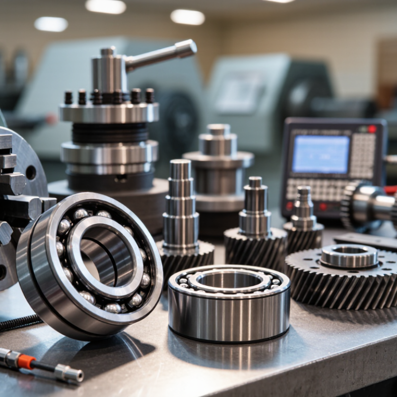
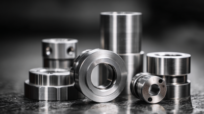
By 2026, global buyers will evaluate lathe machine parts beyond price and basic compatibility. Accuracy, service life, traceability, and delivery reliability will matter equally. A spindle bearing may look insignificant, yet one damaged bearing can create vibration, scrap, and costly downtime. The same risk applies to chucks, tool posts, lead screws, gears, tailstocks, guideways, coolant systems, and CNC control components.
Market data supports this wider view. Fortune Business Insights valued the global CNC machine market at approximately USD 88.56 billion in 2023. Its report projects the market to reach about USD 140.78 billion by 2032. These figures indicate stronger demand for replacement and precision components. Meanwhile, the International Federation of Robotics continues reporting sustained automation investment across automotive, electronics, and metalworking industries. Those factories need dependable parts, not attractive specifications alone.
Professor Yusuf Altintas, a leading machining researcher, is often quoted as saying, “The machine tool is the mother of all machines.” His observation explains why component quality deserves careful attention. A lathe is only as stable as its weakest functional part. However, no ranking can fit every workshop. A heavy steel facility may prioritize rigidity, while a small job shop may value quick changeover and affordable maintenance. That distinction is easy to overlook.
This guide examines the top types of lathe machine parts for global buyers in 2026. It compares practical functions, material choices, accuracy expectations, supplier evidence, and maintenance concerns. Buyers should verify measurements independently. Catalog language is not proof. That may sound obvious, but mistakes still happen.
Lathe machine parts are components that hold, rotate, guide, or cut a workpiece. The bed supports the machine and keeps major assemblies aligned. The headstock contains the spindle, which transfers rotation to the chuck or faceplate. A chuck grips round or irregular stock with adjustable jaws. The tailstock supports long workpieces and can hold drills or reamers. It is often overlooked during basic inspections.
The carriage moves the cutting tool along the bed. Its cross-slide controls movement across the workpiece, while the tool post secures the cutter. The lead screw supports thread cutting, and the feed rod supports regular automatic movement. These parts can be classified as structural, workholding, motion-transmission, or tooling components. This classification helps buyers compare specifications, but it is not perfect. Some parts serve two functions, depending on the machine design.
Tips: Check dimensions, material, mounting accuracy, and surface finish before purchasing. Ask for measured tolerances, not only catalog descriptions. Inspect threads and keyways closely; small damage can cause visible vibration. Keep a record of operating speed and load. In my experience, many failures begin with incorrect alignment rather than weak material. That assumption deserves review. A replacement part may fit physically but still perform poorly if its hardness, balance, or lubrication needs differ.
Global buyers should inspect a lathe by function, not appearance. Grand View Research valued the global machine tools market at approximately USD 86.8 billion in 2023. That scale reflects sustained demand for reliable structural parts. The bed carries the machine and absorbs cutting vibration. A rigid, accurately leveled bed improves surface finish and dimensional stability. Cast iron remains common because it dampens vibration effectively. Still, rigidity alone does not guarantee accuracy.
The headstock houses the spindle, bearings, gears, and drive system. The spindle transfers torque to the chuck or collet. Its runout directly affects concentricity. A practical inspection should measure runout with a calibrated dial indicator. The tailstock supports long workpieces and holds drills or reamers. Misalignment can create tapered shafts and uneven holes. Small errors become expensive quickly. The carriage includes the saddle, cross slide, apron, and tool post. These parts control tool movement across the workpiece. A worn cross slide may show backlash during manual adjustment.
The lead screw and feed rod govern thread cutting and automatic feed. CNC versions add servo drives, encoders, and a controller. Reports from MarketsandMarkets project continued growth in CNC machine tools through the decade, driven by automation and precision production. Buyers should check compatibility, replacement access, lubrication paths, and documented accuracy. Specifications can look impressive. Factory-floor verification matters more. I would not rely on a catalog tolerance without test cuts. Even experienced teams sometimes overlook the apron, although it controls several daily adjustments. Reliability is built from small interfaces, not one impressive component.
2026 Top Types of Lathe Machine Parts for Global Buyers
Cutting, holding, driving, and supporting parts determine a lathe’s real working ability. Grand View Research estimated the global CNC machine tools market above USD 80 billion in 2023. Mordor Intelligence also forecasts steady growth through 2030, although market definitions differ. This expansion increases demand for compatible replacement parts. Cutting parts include tool posts, holders, inserts, and boring bars. Carbide inserts handle hard alloys and repeated production. High-speed steel remains practical for softer materials and small workshops. Small errors multiply.
Holding parts secure the workpiece. Three-jaw chucks offer quick centering for round stock, while four-jaw chucks allow independent adjustment. Collets provide better repeatability for smaller diameters. Buyers should check chuck diameter, mounting thread, jaw travel, and measured runout. Driving parts transfer power from the motor to the spindle. Typical items include spindle shafts, gears, belts, couplings, and speed-control components. Match torque ratings carefully. An oversized belt may still slip under heat.
Supporting parts preserve alignment during cutting. The bed carries the carriage, while cross-slides control tool movement. Tailstocks support long shafts with centers or drill tools. Steady rests reduce vibration on slender workpieces. ISO 230 testing guidance helps evaluate geometric accuracy and positioning performance. However, a report figure cannot replace inspection on the actual machine. Ask suppliers for material certificates, tolerance data, inspection methods, and clear compatibility drawings. Some catalogs still use “precision” without defining it. That deserves a second look.
| Part Category | Lathe Part | Primary Function | Common Materials | Typical Specifications | Suitable Tasks | Selection Considerations |
|---|---|---|---|---|---|---|
| Cutting Parts | Turning Tool Holder | Secures a replaceable cutting insert and maintains a fixed cutting geometry during external or internal turning. | Alloy steel body; carbide or coated carbide inserts. | Common shank sizes include 10 × 10 mm, 12 × 12 mm, 16 × 16 mm, and 20 × 20 mm. Insert nose radii commonly range from 0.2 to 1.2 mm. | Facing, rough turning, finish turning, and shoulder machining. | Match the holder orientation, shank size, insert shape, and workpiece material. |
| Cutting Parts | Boring Bar | Supports an internal cutting insert for enlarging, correcting, or finishing pre-drilled holes. | Alloy steel, carbide, or carbide-reinforced steel. | Typical diameters range from 6 to 32 mm for general-purpose holders. Longer bars require greater rigidity and reduced cutting loads. | Internal turning, stepped bores, and internal shoulder work. | Choose the largest practical diameter and the shortest overhang to reduce vibration. |
| Cutting Parts | Parting and Grooving Tool | Cuts narrow slots or separates a completed component from bar stock. | High-speed steel, carbide, or coated carbide. | Blade widths commonly range from 1.5 to 5 mm. Cutting depth depends on blade height, rigidity, and workpiece diameter. | Parting-off, external grooving, face grooving, and relief grooves. | Use a rigid setup, correct blade height, and suitable chip evacuation for the workpiece material. |
| Cutting Parts | Threading Tool | Forms external or internal screw threads by moving at a synchronized feed rate. | High-speed steel or coated carbide with a ground or molded profile. | Common thread profiles include 60° metric or Unified profiles, 55° Whitworth profiles, and trapezoidal profiles. | External threads, internal threads, and lead-screw-related machining. | Confirm thread angle, pitch, hand direction, insert profile, and required number of passes. |
| Cutting Parts | Drill Chuck and Twist Drill | Holds a drill and produces an axial hole before boring, reaming, or tapping. | Hardened steel chuck; high-speed steel or carbide drill. | Keyed and keyless chucks commonly cover approximately 1 to 13 mm drill capacities. Drill diameters vary according to the required hole size. | Center drilling, pilot drilling, and general hole making. | Check chuck capacity, tailstock taper, drill runout, and coolant access. |
| Holding Parts | Three-Jaw Self-Centering Chuck | Clamps round, hexagonal, or other regular-shaped workpieces while automatically centering them. | Cast iron or steel body; hardened steel jaws. | Common nominal sizes include 80, 100, 125, 160, 200, 250, and 315 mm. Exact gripping range depends on jaw type and chuck design. | Fast setup for concentric bar work and general turning. | Select a chuck diameter compatible with spindle size, workpiece diameter, and machine speed. |
| Holding Parts | Four-Jaw Independent Chuck | Holds square, rectangular, irregular, or eccentric workpieces with each jaw adjusted independently. | Cast iron or steel body; hardened or replaceable steel jaws. | Typical sizes range from approximately 100 to 400 mm. Independent adjustment allows intentional eccentric positioning. | Irregular work, eccentric turning, and precise alignment of non-round parts. | Requires dial-indicator setup; select jaw travel and maximum swing carefully. |
| Holding Parts | Collet Chuck and Collet | Provides accurate, repeatable gripping for small cylindrical or hexagonal workpieces. | Hardened alloy steel. | Typical collet systems cover workpiece ranges from below 1 mm to more than 30 mm, depending on the system and collet size. | Small-diameter parts, secondary operations, and production work requiring repeatable concentricity. | Match the collet nose, drawtube or actuator, workpiece shape, and required gripping range. |
| Holding Parts | Soft Jaws | Provide customized gripping surfaces that can be bored to match a workpiece for improved location and reduced marking. | Low-carbon steel or machinable alloy steel. | Available in standard stepped forms for common chuck sizes; the gripping profile is machined to the finished or reference diameter. | Precision second operations, thin-wall parts, and repeat production. | Bore the jaws under clamping pressure and maintain adequate gripping length. |
| Holding Parts | Faceplate and Clamping Set | Supports workpieces that cannot be safely held in a standard chuck. | Cast iron or steel faceplate; steel clamps, studs, and nuts. | Faceplate diameters commonly range from approximately 160 to 500 mm, depending on lathe swing and spindle capacity. | Large, flat, irregular, or offset components. | Balance the setup, protect the ways, and verify clearance before starting the spindle. |
| Driving Parts | Drive Plate and Lathe Dog | Transfers spindle rotation to a workpiece mounted between centers. | Steel or cast iron drive plate; steel lathe dog. | Drive-plate diameter and center bore must match the spindle or center arrangement. Dogs are selected by workpiece diameter. | Turning between centers where the full circumference must remain accessible. | Ensure secure dog contact and use a guarded setup to reduce exposure to rotating parts. |
| Driving Parts | Live Center | Supports the workpiece at the tailstock while its bearing-supported point rotates with the workpiece. | Hardened alloy steel; precision bearings. | Common Morse taper interfaces include MT2, MT3, and MT4. Point angles commonly include 60° for general turning. | Turning between centers and supporting long or slender workpieces. | Check taper compatibility, maximum speed, bearing condition, and point geometry. |
| Driving Parts | Mandrel | Locates and drives a hollow workpiece from its internal bore. | Hardened steel or alloy steel. | Fixed, expanding, and stepped types are available. The locating diameter is sized to the workpiece bore. | Machining outside diameters, faces, and features on bored components. | Use a clean, accurately sized bore and avoid excessive expansion that could distort thin-wall parts. |
| Driving Parts | Taper Attachment | Guides the tool at a controlled angle to produce a tapered external or internal surface. | Steel slide, guide bar, and adjustment components. | Typical taper angles depend on attachment travel and guide-bar adjustment; setup is based on taper per unit length or included angle. | Long tapers, Morse-style tapers, and repeat taper production. | Confirm cross-slide travel, attachment length, taper ratio, and machine mounting compatibility. |
| Supporting Parts | Tailstock | Supports the free end of a workpiece and holds drills, reamers, taps, and centers. | Cast iron or cast steel body; hardened quill and spindle components. | Quill travel commonly ranges from approximately 75 to 150 mm on general-purpose engine lathes. Taper interfaces often include MT2 to MT5. | Center support, drilling, reaming, tapping, and turning long workpieces. | Check alignment with the headstock, quill travel, taper size, and base locking condition. |
| Supporting Parts | Steady Rest | Provides adjustable radial support for long or slender workpieces during machining. | Cast iron or steel frame; bronze, brass, roller, or bearing contact points. | Capacity is defined by the maximum workpiece diameter that can pass through the support fingers; common ranges are approximately 10 to 150 mm. | Long-shaft turning, boring, threading, and operations with high cutting pressure. | Set the fingers with minimal clearance and lubricate contact surfaces when required. |
| Supporting Parts | Follower Rest | Moves with the carriage and supports the workpiece close to the cutting tool. | Cast iron or steel body; adjustable bronze, brass, or roller fingers. | Capacity depends on the tool-post or carriage mounting arrangement and the available finger adjustment range. | Slender shaft turning, especially when tool pressure causes deflection. | Position the support near the cutting zone and adjust it without forcing the workpiece away from the tool. |
| Supporting Parts | Tool Post | Clamps and positions the cutting tool on the compound rest or cross slide. | Steel, alloy steel, or hardened tool steel. | Common manual-lathe styles include four-way and quick-change designs. Tool capacity must suit the holder shank and machine center height. | General turning, facing, threading, grooving, and tool changes. | Match the post to the center height, compound-rest mounting, tool size, and required repeatability. |
| Supporting Parts | Centers | Locate and support a workpiece through a center hole when machining between centers. | Hardened tool steel or carbide-tipped steel. | Common included point angles are 60°. Morse taper sizes are selected according to the headstock or tailstock spindle. | Accurate shaft turning, inspection, grinding preparation, and repeat setups. | Use matching center angles, clean center holes, and adequate lubrication for dead-center applications. |

Selecting lathe parts for industrial applications starts with the machine, not the catalogue. Identify the model, swing, spindle nose, thread standard, load range, and operating speed. A three-jaw chuck suits repeatable round work, while a four-jaw chuck supports careful alignment of irregular stock. Tool posts, collets, bearings, lead screws, belts, and tailstock components must match interface dimensions. Measure worn parts with calibrated tools; memory is not enough. Fit matters.
Global buyers should request material grades, heat-treatment records, tolerance tables, surface-finish data, and inspection reports. For precision work, ask how runout was measured and at which reference point. “High accuracy” means little without numbers. Check thread direction, electrical requirements, packaging strength, and replacement availability before ordering. Moisture-resistant wrapping can protect bearings during long transit. A realistic production schedule matters too. Cheap parts can create expensive downtime.
Samples or first-article inspections reduce risk when similar machines use different dimensions. Compare each part with the drawing, not only the old component, because wear may distort critical surfaces. Keep serial records, photographs, and measured results for repeat purchasing. One practical lesson is uncomfortable: the fastest quotation is not always the safest choice. A perfectly machined part can still fail when its thread standard is wrong. Ask clear questions. Verify every critical interface before installation.
Maintenance begins with the spindle, chuck, bearings, drive belts, and lubrication system. A small bearing defect can create visible chatter on a finished shaft. McKinsey reports that predictive maintenance can reduce machine downtime by 30–50%. That figure is useful, but workshop results vary widely.
Inspect components against the original drawings, tolerance ranges, and operating temperature. Compatibility involves more than diameter. Check thread form, mounting pattern, speed rating, material, and control-system interface. ISO 1940-1 supports balancing requirements for rotating parts, while ISO 9001 encourages documented inspection and traceability. Keep batch records.
Do not trust appearance alone.
A replacement tailstock quill may look identical, yet its steel grade or surface hardness can differ. Measure runout with a dial indicator before production. Record readings at cold and warm conditions.
The U.S. Department of Energy’s maintenance guidance links planned maintenance with lower repair costs and improved equipment reliability. Still, maintenance schedules are not perfect; excessive lubrication can damage seals, and missed alignment checks can waste an entire shift.
Global buyers should request material certificates, dimensional reports, hardness results, and clear packaging instructions. Supplier claims need verification.