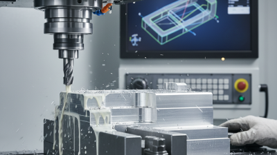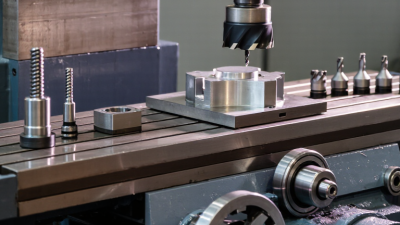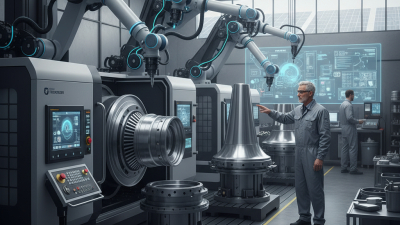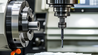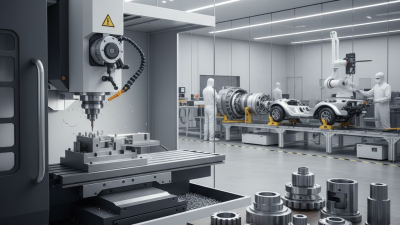
A milling machine is more than a motor, cutter, and worktable. It is a coordinated system where the spindle, arbor, collet, feed mechanism, table, and control unit shape metal with measured force. These milling machine parts determine cutting accuracy, surface finish, tool life, and operator safety. A loose collet can leave visible chatter marks. Poor lubrication can quietly damage a spindle bearing.
The global market reflects this importance. Grand View Research reported strong growth in the computer numerical control machine market, driven by automation, aerospace production, and precision manufacturing. Fortune Business Insights also identified rising demand for advanced machine tools and digitally controlled equipment. These reports describe market direction, not a guarantee of performance. Real results still depend on maintenance, alignment, tooling, and operator experience.
John Saunders, a CNC educator and manufacturing specialist, often emphasizes a practical principle: “The machine only performs as well as the process around it.” That idea deserves attention. Even an expensive milling machine can produce inconsistent parts when inspection is weak or setup measurements are rushed. This guide examines the main milling machine parts, their functions, and their influence on machining results. It also considers common design compromises, because not every component offers maximum speed, rigidity, and flexibility at once. Readers should compare manufacturer specifications with recognized standards, including ISO 230 guidance for machine-tool accuracy. Small errors matter. A few microns can change the final fit.
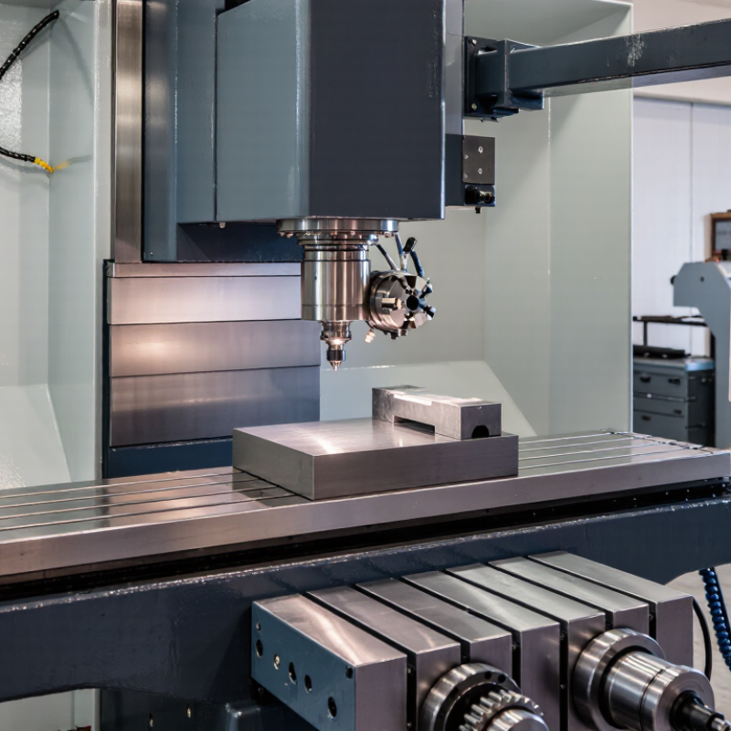
A milling machine is a machine tool that removes material with a rotating cutter. The workpiece is held securely while the cutter shapes its surface. It removes material. Unlike a drill, it can cut along several controlled directions. This makes it useful for slots, flat faces, steps, holes, and angled features.
The main parts support this basic function. The base carries the machine and reduces vibration. The column provides a rigid vertical structure. The table holds the workpiece or a fixture. The saddle and knee move the table across different axes. The spindle rotates the cutting tool, while the motor supplies power. Controls adjust feed movement, speed, and cutting depth.
In practical machining, accuracy depends on more than machine design. A clean table, sharp cutter, and correctly tightened workholding setup matter greatly. I have found that small chips under a fixture can change a dimension noticeably. The operator must also match cutting speed and feed to the material and tool. Excessive force may cause chatter, heat, or a damaged edge. No setup is perfect. Measurements should be checked during the operation, not only afterward. Some beginners focus on spindle speed and overlook alignment. That mistake is understandable, but it deserves correction. A milling machine performs best when rigidity, controlled movement, and careful inspection work together.
A milling machine shapes solid material with a rotating cutter. The cutter removes small chips as it meets the workpiece. Unlike a drill, it can cut sideways, create slots, flatten faces, and produce angled surfaces.
The main parts support this action. The motor drives the spindle, which holds the cutter firmly. The table carries the workpiece, often in a vise, while handwheels or powered axes control movement. The column and base resist cutting forces. That resistance matters. If the setup flexes, the cutter may chatter, leaving ripples instead of a clean surface. Cutting fluid can reduce heat and carry chips away, although its use depends on the material and operation.
Material removal begins when the rotating teeth enter the workpiece. Each tooth takes a measured chip, called feed per tooth. Spindle speed, feed rate, depth of cut, and cutter geometry must work together. A deep pass is faster in theory, but it can overload the tool or distort a thin part. I learned this through an avoidable setup mistake: clamping pressure marked the surface and shifted the measurement. Now I check rigidity, tool reach, chip color, and sound before increasing the feed. The sound is useful, but not proof. A quiet cut can still hide excessive tool wear or inaccurate dimensions.
A milling machine removes material with a rotating cutter while the workpiece remains secured. Its main structure controls accuracy, stiffness, and operator safety. In practical use, the frame matters first. Usually called the base and column, it carries the table, motor, and cutting forces. A heavy base reduces vibration. Not always enough. Poor leveling can still produce chatter and uneven dimensions.
The column supports the spindle head and guides vertical movement. The spindle holds the tool and transfers torque through bearings. Its alignment directly affects hole position and surface finish. The knee, saddle, and table form the positioning system. The knee moves vertically. The saddle travels across the column. The table moves lengthwise and clamps the vise or fixture. These parts need clean ways and controlled lubrication. Tiny chips can distort movement. This is easy to overlook.
A feed mechanism controls travel speed and cutting consistency. Manual handwheels provide feedback, while powered feeds maintain steadier motion. The workholding device must resist lifting and sideways movement. Clamps should sit close to the supported area. The coolant system, guards, and emergency stop support safer operation and longer tool life. In my experience, operators often inspect the cutter before checking table alignment. That habit deserves reconsideration. Every structural part shares the load, but not equally. An accurate machine can still produce poor work when setup discipline is weak.
A milling machine removes material with a rotating cutter while the workpiece moves against it. Its main parts include the spindle, table, column, knee, and feed controls. Each configuration changes how force, accuracy, and access are managed.
A vertical milling machine keeps the spindle above the table. It suits slots, pockets, drilling, and angled surfaces. The knee usually moves vertically, while the table travels across two horizontal axes.
A horizontal mill positions the spindle sideways. Its arbor supports heavier cutters and often improves chip removal during deep cuts. Universal configurations add table rotation, which helps produce helical grooves and angled features.
CNC milling machines use programmed axis movement. Three-axis systems cover many general jobs, but four- and five-axis machines reach complex surfaces with fewer setups. Bed-type machines support the table on a rigid base, making them useful for larger workpieces. Gantry mills span the work area with a bridge structure and handle broad plates or molds.
The labels can overlap.
In practical work, rigidity matters more than a machine’s category alone. I have seen a capable vertical mill produce poor surfaces because the tool extended too far. A loose knee, worn leadscrew, or dirty table can also create measurable error. Check backlash, spindle runout, and table alignment before trusting tight dimensions. Cooling method, cutter diameter, and workholding should match the material and operation. A configuration that looks ideal on paper may still feel awkward beside the actual part.
A milling machine removes material with a rotating cutter and controlled table movement. Its spindle holds the cutting tool, while the table supports the workpiece. The saddle and knee provide horizontal and vertical adjustment. These parts work together during cutting, drilling, slotting, and surface finishing. Operators use milling machines for metal components, repair work, prototypes, and small production batches.
Key applications require different operating choices. A deep slot needs steady feed control and proper chip clearance. A wide surface may need several lighter passes instead of one aggressive cut. Secure the workpiece firmly before starting. A loose clamp can damage the part or create dangerous movement. Select cutting speed and feed according to the material, cutter diameter, and machine rigidity. Check tool reach carefully. Excessive extension can cause vibration and poor surface quality. Even experienced operators can overlook a small alignment error. It is worth checking the setup again.
Tips: Keep cutting edges sharp and remove chips with a brush, not bare hands. Watch for unusual noise, heat, or vibration. Stop the machine before measuring or adjusting the workpiece. Record successful speeds and feeds for future jobs, but do not copy them blindly. Material hardness and tool condition can change the result. I would also inspect the first finished surface closely; a clean appearance does not always prove accurate dimensions.
| Category | Item | Description or Function | Typical Applications or Considerations |
|---|---|---|---|
| Machine Definition | Milling machine | A machine tool that removes material with a rotating, multi-edge cutting tool while the workpiece and/or tool moves along controlled axes. | Used to produce flat surfaces, slots, pockets, contours, holes, and complex three-dimensional forms. |
| Machine Type | Vertical milling machine | The spindle is oriented vertically, allowing the cutting tool to move downward toward the workpiece. | Suitable for face milling, end milling, drilling, slotting, and general-purpose workshop work. |
| Machine Type | Horizontal milling machine | The spindle is arranged horizontally, often supporting an arbor and multiple cutters. | Effective for heavy cuts, long slots, side milling, and production work requiring good chip evacuation. |
| Machine Type | CNC milling machine | A computer-controlled machine that follows programmed tool paths and coordinates multiple axes. | Used for repeatable production, complex profiles, tight tolerances, and reduced manual intervention. |
| Main Part | Base | The rigid foundation that supports the machine and helps absorb vibration during cutting. | Must be installed on a stable, level surface to maintain accuracy and reduce vibration. |
| Main Part | Column | The vertical structural member that supports the spindle head and guides or houses key drive components. | Provides rigidity and alignment for vertical movement and cutting operations. |
| Main Part | Knee | A vertically adjustable casting that supports the saddle and table on many conventional milling machines. | Allows the workpiece height to be adjusted relative to the spindle. |
| Main Part | Saddle | The component between the knee and table that commonly provides movement across the machine. | Supports cross-feed movement and helps position the workpiece accurately. |
| Main Part | Worktable | A grooved platform used to support and secure the workpiece, vise, fixture, or rotary table. | T-slots allow clamping hardware and fixtures to be positioned for different operations. |
| Main Part | Spindle | The rotating shaft that holds and drives the milling cutter or tool holder. | Speed, torque, runout, and tool compatibility directly influence cutting performance. |
| Main Part | Spindle head | The assembly containing the spindle, bearings, drive elements, and related controls. | Maintains spindle alignment and may provide quill or angular adjustment on some machines. |
| Main Part | Milling cutter | A rotary cutting tool with one or more teeth that removes material from the workpiece. | Cutter type, diameter, tooth count, material, and geometry should match the workpiece and operation. |
| Workholding | Vise or fixture | A device that locates and clamps the workpiece during machining. | Secure clamping is essential for dimensional accuracy, surface quality, and operator safety. |
| Cutting Operation | Face milling | Machining a broad, generally flat surface with the cutter axis approximately perpendicular to the surface. | Often used to improve flatness, remove stock, or prepare a reference surface. |
| Cutting Operation | End milling | Uses the end and peripheral edges of a cutter to machine slots, pockets, shoulders, and contours. | Common in toolmaking, fixture production, mold work, and general component machining. |
| Cutting Operation | Drilling and boring | Drilling creates holes, while boring enlarges or improves the accuracy of existing holes. | Tool alignment, rigidity, feed rate, and chip removal affect hole quality. |
| Key Parameter | Spindle speed | The rotational speed of the cutter, normally expressed in revolutions per minute. | Should be selected according to cutter diameter, cutting speed, tool material, and workpiece material. |
| Key Parameter | Feed rate | The rate at which the cutter or workpiece advances through the material. | An excessive feed can overload the tool, while an insufficient feed may cause rubbing and heat buildup. |
| Key Parameter | Depth and width of cut | Depth is the material removed in one pass; width is the portion of the cutter engaged with the workpiece. | Smaller cuts can reduce cutting forces, deflection, heat, and vibration when rigidity is limited. |
| Operating Consideration | Material selection | Workpiece materials may include aluminum, steel, stainless steel, cast iron, brass, plastics, and composites. | Tool geometry, cutting data, coolant strategy, and chip control must be adapted to the material. |
| Operating Consideration | Coolant and chip control | Coolant can help control heat and flush chips, while dry machining may be suitable for selected materials and tools. | Avoid chip recutting, ensure adequate ventilation, and follow the cutting-tool and machine guidance. |
| Operating Consideration | Safety | Safe operation requires guarding, eye protection, secure workholding, correct tool installation, and controlled machine access. | Never touch rotating tools or remove chips by hand; stop the machine before adjustments, cleaning, or measurement. |
| Typical Application | Parts and industries | Milling machines produce machine bases, brackets, gears, housings, molds, dies, fixtures, and precision components. | Widely applied in maintenance, fabrication, automotive, aerospace, medical-device, energy, and general manufacturing work. |