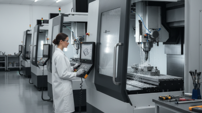
Why Choose CNC Milling Machine Tools?
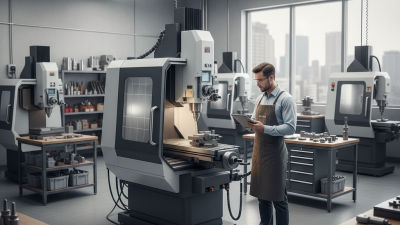
Choosing milling machine tools is a practical decision for shops that need repeatable accuracy, flexible production, and controlled costs. CNC milling machines guide cutting tools through programmed paths. They can produce slots, pockets, curved surfaces, and precise holes from digital designs. Thomas W. Kurfess, a respected manufacturing engineer and former U.S. presidential manufacturing adviser, describes the purpose clearly: “Manufacturing is the process of converting raw materials into products.”
That conversion becomes more dependable when the machine, tooling, and process work together. A rigid CNC mill can hold tight dimensions across repeated aluminum or steel components. Its operator can inspect the first part, adjust offsets, and monitor tool wear before defects multiply. Modern controls also record machining data, helping engineers improve cycle times and production consistency.
Small details matter.
A clean fixture prevents movement. Proper coolant reduces heat. A sharp end mill leaves a cleaner surface. These benefits explain why many manufacturers select milling machine tools for prototypes, repair parts, and medium-volume production. However, CNC equipment is not a shortcut around engineering judgment. Poor workholding, incorrect feeds, or an unsuitable tool can still ruin an expensive workpiece. That limitation deserves attention. The best machine cannot rescue a careless setup.
Reliable selection should include spindle speed, travel range, motor power, control features, service support, and operator training. Buyers should also compare real production requirements, not impressive brochures. A carefully matched CNC milling machine can improve accuracy, reduce manual repetition, and create a more stable manufacturing process. It is valuable, but only when used thoughtfully.
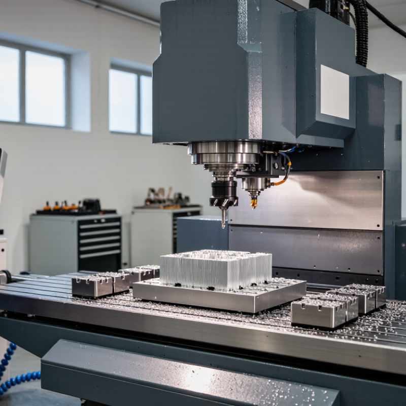
A CNC milling machine tool is a computer-controlled system that removes material from a solid workpiece. It uses rotating cutters to create slots, holes, pockets, contours, and precise surfaces. The machine follows programmed movements along several axes. These movements guide the spindle and cutting tool around metal, plastic, wood, or composite materials. Unlike a manual mill, it can repeat complex paths with consistent positioning. However, CNC does not mean automatic perfection. A poor drawing, loose fixture, or worn cutter can produce the same error repeatedly.
In practical machining, the process usually begins with a digital design and manufacturing program. The operator selects cutting speeds, feed rates, tool sizes, and workholding methods. These choices depend on material hardness, part shape, and required tolerance. A rigid setup reduces vibration and protects surface quality. Coolant or air may help control heat and chips. Even experienced users inspect the first part carefully. Small mistakes still happen, especially when tool offsets or coordinate settings are misunderstood.
Tips: Secure the workpiece firmly. Check tool length offsets before cutting. Run a simulation when possible. Measure critical features with suitable instruments. Keep chips away from moving components, and review the program line by line before production. A short test cut can prevent expensive material waste.
CNC milling machines convert digital instructions into controlled cutting movements. A programmer creates a 3D model, then generates toolpaths and G-code. The controller reads each command and coordinates the spindle, table, and cutting tool. Small steps matter.
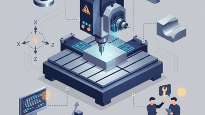
During operation, the workpiece is clamped firmly on the table. The spindle rotates a cutter while linear axes move along X, Y, and Z. Some machines also rotate the workpiece for angled surfaces. Encoders report axis positions, helping the controller correct movement in real time. Coolant carries heat away and flushes chips from the cut. According to the U.S. National Institute of Standards and Technology, accurate process monitoring can reduce defects by identifying variation during production rather than after inspection.
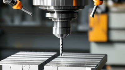
Tool selection depends on material, depth, speed, and feed rate. A carbide cutter may remove aluminum quickly, while hardened steel demands slower settings and stronger support. The International Organization for Standardization’s ISO 230 series defines tests for machine-tool accuracy and performance. These tests show why calibration is not optional. A machine can repeat a programmed path, yet still produce an incorrect part if thermal expansion or tool wear is ignored.
The process is precise, but not flawless. A dull edge can leave visible lines on a pocket wall. Excessive feed may cause vibration. That assumption can fail. Operators still inspect dimensions with gauges or coordinate measuring equipment, compare results with the drawing, and adjust the next cycle. Grand View Research reported continued growth in the global CNC machine market, reflecting demand for repeatable production and tighter control. The real advantage is controlled consistency, not automatic perfection.
CNC milling machines convert digital drawings into controlled cutting movements. They can produce slots, pockets, holes, and contoured surfaces with consistent accuracy. In a well-prepared setup, the same program can repeat a part many times. That matters.
A major advantage is repeatability. Operators can inspect the first piece, adjust offsets, and continue production with fewer manual corrections. Modern control systems also support multiple axes, reducing the need to reposition complex workpieces. This can shorten setup time and improve surface consistency. Tool libraries, coolant control, and automatic probing can make daily work more predictable. However, these features depend on correct calibration and disciplined operation.
CNC milling machines also handle materials such as aluminum, steel, plastics, and engineering alloys. Cutting speed, feed rate, tool geometry, and workholding must match each material. A powerful machine cannot repair a poor setup. I have seen small errors in clamping create visible marks across an otherwise accurate part. It is easy to blame the machine, but the real cause may be worn tooling or an unverified program. Regular inspection with calibrated instruments helps confirm dimensions before problems spread. Efficiency is valuable, but careful judgment still controls the result.
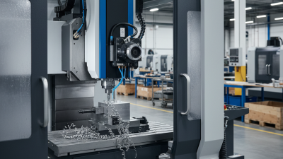
CNC milling machines convert digital designs into accurate, repeatable components. Vertical mills suit general workshops, prototypes, and plates with accessible top surfaces. Horizontal mills handle heavier cuts and improve chip removal on large workpieces. Three-axis machines cover many routine parts. Four- and five-axis models reach angled surfaces, turbine shapes, and complex medical components with fewer setups.
Applications depend on geometry, material, tolerance, and production volume. A vertical machining center may produce aluminum housings, steel brackets, or fixture plates efficiently. A five-axis machine can reduce repositioning when machining curved aerospace structures. However, more axes do not automatically improve every job. They can increase programming demands, inspection needs, and setup risks. Shop-floor results often depend on tool selection, workholding, coolant control, and operator judgment. A small alignment error can leave visible steps on a finished surface. That detail is easy to underestimate.
Tips: Match the machine to the part, not the other way around. Check spindle power, travel range, table capacity, and tool access before purchasing. Use a rigid fixture and verify the work offset carefully. Start with conservative cutting parameters for unfamiliar materials. Review chips and surface finish during the run. Some recommendations may need adjustment after testing, because real cutting conditions rarely match the catalog perfectly.
| CNC Milling Machine Type | Typical Axes | Key Characteristics | Common Materials | Typical Applications | Best Suited For |
|---|---|---|---|---|---|
| Vertical Milling Machine | 3 axes; 4 or 5 axes optional | Vertically oriented spindle, accessible work area, and relatively simple programming and setup. | Aluminum Steel Brass Plastics | Slots, pockets, drilling, face milling, contours, and general-purpose component production. | Prototype work, repair parts, job shops, and low-to-medium production volumes. |
| Horizontal Milling Machine | 3 axes; rotary or additional axes optional | Horizontally oriented spindle improves chip evacuation and supports deep cuts and multiple-sided machining. | Steel Cast Iron Aluminum Titanium | Deep slots, heavy material removal, side milling, gearbox components, and large structural parts. | High material-removal rates, repeat production, and large or heavy workpieces. |
| 3-Axis CNC Milling Machine | X, Y, and Z linear axes | Moves the cutting tool or workpiece along three perpendicular axes without automatically rotating the part. | Aluminum Steel Brass Engineering Plastics | Flat surfaces, pockets, holes, 2.5D profiles, fixtures, brackets, and basic molds. | Cost-effective machining of prismatic parts with accessible features. |
| 4-Axis CNC Milling Machine | X, Y, Z, plus one rotary axis | Adds rotary positioning, allowing several sides of a part to be machined with fewer setups. | Aluminum Steel Brass Wood | Indexing around cylindrical parts, side drilling, impellers, cams, and components with features on multiple faces. | Parts requiring improved access and reduced setup time without continuous 5-axis motion. |
| 5-Axis CNC Milling Machine | Three linear axes plus two rotary axes | Positions the tool or workpiece from multiple angles, enabling complex surfaces and fewer workholding operations. | Titanium Aluminum Steel Composites | Aircraft components, turbine blades, medical implants, complex molds, and contoured aerospace structures. | Complex geometries, tight access areas, high accuracy, and reduced repositioning. |
| Bed-Type Milling Machine | Usually 3 axes; additional axes optional | Workpiece rests on a rigid bed while the spindle head provides controlled vertical or angular movement. | Steel Cast Iron Aluminum | Large plates, dies, molds, machine bases, and components requiring stable heavy cutting. | Large workpieces, rigidity-demanding operations, and heavy-duty milling. |
| Gantry or Bridge Mill | 3 to 5 axes | Bridge-supported spindle structure provides a large work envelope and stable access over oversized parts. | Aluminum Steel Composites Foam | Large molds, aerospace panels, wind-energy components, shipbuilding parts, and structural assemblies. | Oversized workpieces and large-format precision machining. |
| CNC Mill-Turn Center | Typically 3 linear axes plus turning and live-tool axes | Combines turning and milling operations in one machine, reducing transfers between separate machines. | Steel Stainless Steel Aluminum Brass | Shafts, flanges, threaded parts, valve bodies, fittings, and components with both rotational and milled features. | Complete machining of complex rotational parts with fewer setups. |
| CNC Router | Usually 3 axes; 4 or 5 axes available | High-speed spindle or cutting system designed for sheet goods, non-ferrous metals, plastics, and lightweight materials. | Wood Plastic Aluminum Foam | Signs, cabinetry, furniture panels, model making, engraving, and composite sheet cutting. | Large-area cutting, decorative work, and rapid machining of softer materials. |
The right model can improve repeatability, reduce setup time, and support complex parts. However, selection should begin with production evidence, not attractive specifications. Deloitte’s 2023 Smart Manufacturing and Operations Survey found that 86% of manufacturers expect smart manufacturing to strengthen competitiveness within five years. That shift makes control connectivity and usable production data increasingly important.
include rigidity, spindle speed, axis travel, work envelope, and positional accuracy. Match the machine to actual materials and part sizes. Aluminum may need high speed, while hardened steel demands stiffness and stable cutting.
Check tool capacity, chip evacuation, coolant control, and fixture access. A machine with five axes is not automatically better. It may increase training time and maintenance costs.
Evaluate cycle-time trials with your own tooling. Small details matter. Review service response, spare-parts availability, software compatibility, and total ownership cost.
ISO 230 testing methods can help verify machine-tool accuracy, but shop-floor results may still differ.
Tips:
Request sample cuts before purchasing. Measure surface finish, dimensional drift, vibration, and tool wear. Ask operators to test the interface. Their feedback is often overlooked. Compare energy use during real cycles, not idle demonstrations. A lower purchase price can hide expensive downtime. Also, leave room for honest doubt: forecast volumes may be wrong, and future work may require different tooling. Choose flexible capacity, but avoid paying for unused capability.