
10 Best Lathe Machine Parts for Buyers?
A lathe can look simple from the outside: a spindle turns the workpiece, while a cutting tool removes material. Yet one worn bearing, mismatched chuck, or poorly fitted belt can affect accuracy and downtime. For buyers comparing lathe machine parts, the “best” choice depends on the machine model, workload, material, and required tolerances. There is no universal winner.
The market context is significant. Grand View Research estimated the global machine-tool market at approximately USD 86.5 billion in 2023 and projected continued growth through 2030. Its report covers a broad range of machine tools, not lathe components alone, but it reflects sustained investment in machining equipment. That matters. Buyers should look beyond purchase price and confirm compatibility, material quality, dimensional specifications, and supplier documentation. A low-cost part is not a bargain if it causes repeat setup or premature wear.
This guide reviews ten commonly purchased components, including chucks, spindles, tool posts, tailstocks, lead screws, bearings, and drive belts. It focuses on practical checks: mounting dimensions, load capacity, runout, lubrication needs, and replacement availability. Where relevant, compare the part against the machine manual and technical drawings rather than relying on a product photo. Small details count. A chuck’s mounting thread or a bearing’s clearance class can decide whether installation is smooth or frustrating. Some listings still omit useful specifications, so buyers may need to ask direct questions before ordering. The recommendations are a starting point, not a substitute for machine-specific verification.
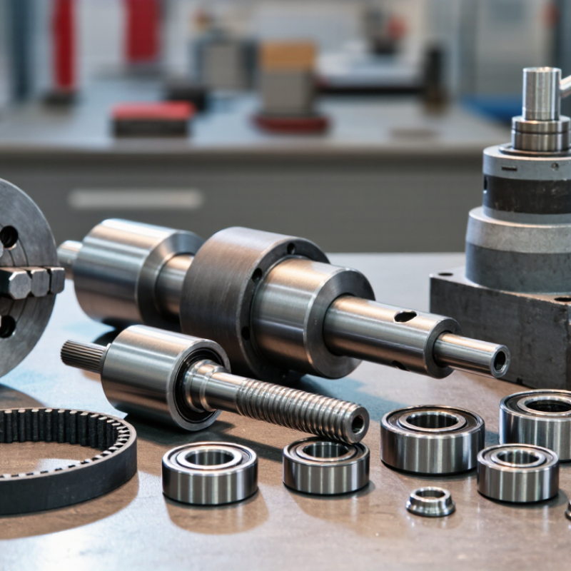
Assess the Bed and Spindle with ISO 230-1 Accuracy Tests
For buyers comparing lathe machine parts, the bed and spindle deserve measured checks, not visual guesses. ISO 230-1:2012 sets out geometric accuracy tests for machine tools under no-load or quasi-static conditions. On the bed, record straightness and alignment readings at several positions, using a calibrated level or straightedge. Write down each deviation in micrometres, the test setup, and the machine’s temperature. Small setup changes matter. A warm bed can give a different reading.
Check spindle alignment against the machine’s reference surfaces, but do not treat ISO 230-1 as a complete spindle-rotation test. ISO 230-7 covers determination of spindle error motion. This distinction matters when a seller provides only one “accuracy” figure. NIST Technical Note 1297 provides a recognized method for evaluating measurement uncertainty; include instrument uncertainty with the reported readings. A neat certificate can still leave questions. Ask for repeat measurements, test conditions, and the actual results—not just a pass mark. Compare those figures with the work you plan to produce, since one universal tolerance cannot describe every lathe or application.
10 Best Lathe Machine Parts for Buyers? - Assess the Bed and Spindle with ISO 230-1 Accuracy Tests
Use this checklist to compare critical lathe components. ISO 230-1 provides methods for testing geometric accuracy under no-load or quasi-static conditions; it does not prescribe one universal pass/fail tolerance for every lathe. The example readings below are illustrative sample data, not certification results. Agree on acceptance limits for the machine’s size, configuration, and intended work before purchase.
| Part | Why It Matters | Buyer’s Measurement or Test | Illustrative Sample Result | What to Confirm Before Purchase |
|---|---|---|---|---|
| 1. Bed and guideways | Supports the carriage and helps maintain alignment along the turning axis. | Check longitudinal straightness and guideway condition with a suitable precision level, straightedge, or measurement setup. Record test length and direction. | Example: 0.015 mm deviation over a 1,000 mm test length. This is a sample reading, not a general limit. | Ask for a documented test method, measurement locations, environmental conditions, and an agreed acceptance tolerance. |
| 2. Spindle and spindle nose | Rotates the workpiece; spindle geometry and condition affect runout and finished-part accuracy. | Measure radial runout at the spindle nose and at a specified position on a precision test bar. Check axial movement using an appropriate indicator setup. | Example: 0.006 mm radial indicator variation at the nose and 0.012 mm at a stated test-bar position. | Confirm the test-bar specification, gauge resolution, measurement position, spindle speed, and whether the result is runout or total indicator reading. |
| 3. Spindle bearings | Support the spindle and influence rotational stability, temperature, noise, and vibration. | Check bearing temperature after the maker’s specified warm-up, listen for abnormal noise, and measure spindle vibration using a defined procedure. | Example: stable temperature during the agreed test period, with no unusual noise reported. A numeric limit must be set for the machine and test method. | Request warm-up conditions, lubrication details, vibration measurement location, and service or adjustment history. |
| 4. Chuck or workholding system | Clamps the workpiece; jaw condition and mounting affect concentricity and safe operation. | Inspect jaw movement and contact condition; indicate a suitable test piece mounted using the agreed clamping procedure. | Example: 0.020 mm indicator variation on the agreed test piece after mounting. Results depend on the chuck, jaws, and setup. | Verify chuck capacity, compatible spindle interface, jaw condition, operating limits, and the repeatability procedure. |
| 5. Carriage and saddle | Guides the cutting tool along the bed and affects straightness during longitudinal feed. | Check carriage travel for smoothness and measure alignment or straightness over a defined travel using a suitable reference and indicator. | Example: smooth travel with no detectable binding during the inspection; record measured deviation over the tested travel. | Inspect for uneven wear, sticking, excessive play, and consistent movement at different positions on the bed. |
| 6. Cross-slide and compound slide | Provide tool movement across and at an angle to the spindle axis. | Measure slide movement against the graduated scale or a reference indicator; check backlash and repeatability after reversing direction. | Example: 0.04 mm measured reversal movement before adjustment. Record the test position and method. | Ask how backlash is adjusted and check whether the slide moves evenly through its usable range. |
| 7. Feed shaft, lead screw, or ball screw | Transmits motion for power feed or thread cutting; wear or pitch error can affect feed consistency. | Inspect the screw and nut, test feed engagement, and verify thread-cutting or axis-positioning performance with a defined procedure. | Example: 0.03 mm reversal movement at a specified carriage position, measured with an indicator. | Identify the screw type and intended function; ask for measured backlash, wear condition, and maintenance requirements. |
| 8. Tailstock and quill | Supports long workpieces or holds drilling tools; alignment is important for straight machining. | Check quill travel and lock action; measure tailstock alignment against a spindle-mounted test bar or other agreed reference. | Example: 0.020 mm offset over the specified test length after alignment. The acceptable value depends on the job and setup. | Confirm quill travel, taper condition, locking stability, adjustment range, and alignment test details. |
| 9. Toolpost and tool holder | Positions and secures the cutting tool; poor clamping can reduce repeatability and surface quality. | Check locking security, seating surfaces, tool-height adjustment, and repeatability after removing and reinstalling the holder. | Example: tool-tip height repeats within 0.02 mm across three reinstallations in a controlled check. | Verify holder compatibility, locking condition, available tool positions, and repeatability with the actual tooling arrangement. |
| 10. Feed gearbox and drive controls | Set spindle and feed functions; correct engagement supports consistent operation and thread cutting. | Operate each specified speed and feed selection; check engagement, displayed or measured spindle speed, and abnormal noise or vibration. | Example: measured spindle speed within 2% of the selected value during a steady-state check; verify against agreed test conditions. | Confirm the available speed and feed range, control accuracy, changeover instructions, and operation under the intended load. |
Related Posts
-

2026 Top Types of Lathe Machine Parts for Global Buyers
-
Discover the Best Techniques for CNC Turning Parts Manufacturing Efficiency
-

2025 Top 5 Essential Lathe Machine Parts You Need for Optimal Performance
-

Why is CNC Lathe Essential for Modern Manufacturing?
-
What is CNC Lathe and How Does It Benefit Your Business?
-

How to Choose the Best CNC Turning Parts Supplier?