
What Are CNC Parts and How Are They Made?
CNC parts are machined components produced through computer-controlled cutting, drilling, turning, or milling. They appear in aircraft brackets, medical housings, automotive shafts, and everyday industrial equipment. Unlike manually operated machining, CNC systems follow digital instructions with repeatable tool movements. A small aluminum block can become a precise valve body within minutes, although the result depends heavily on programming, tooling, material, and inspection.
The market is expanding with advanced manufacturing. Grand View Research reports continued growth in the global CNC machine market, driven by automation, aerospace demand, and tighter production requirements. The U.S. National Institute of Standards and Technology also emphasizes measurement consistency and process control in modern manufacturing environments. These findings explain why manufacturers invest in five-axis machines, simulation software, and in-process inspection. Speed matters. Accuracy matters more.
Making cnc parts usually begins with a 3D CAD model and an engineering drawing. A machinist then selects the material, workholding method, cutting tools, feeds, speeds, and machining sequence. The CAM system converts design geometry into machine-readable toolpaths. After setup, the machine removes material layer by layer. Operators may check dimensions using calipers, micrometers, gauges, or coordinate measuring machines. Standards such as ISO 9001 and ASME Y14.5 support quality planning and geometric control.
Still, CNC production is not automatically perfect. Heat can shift dimensions. Tools wear gradually. Poor fixturing can create vibration marks or hidden distortion. That is why reliable suppliers document inspections, revise programs carefully, and trace material certificates. Industry reports often highlight automation, but practical judgment remains essential. A flawless screen simulation cannot correct an incorrectly loaded workpiece. Understanding this balance helps readers evaluate how CNC parts are designed, manufactured, inspected, and improved.
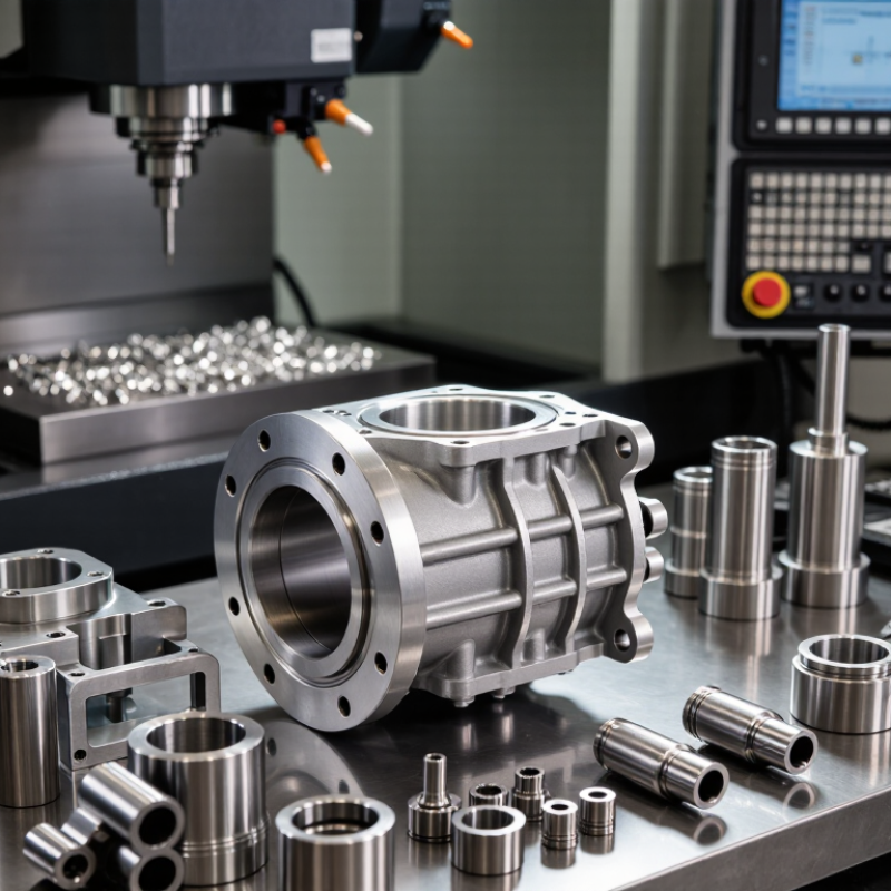
What CNC Parts Are and What They Do
CNC parts are precision components cut from metal, plastic, or composite stock by computer-controlled tools. They include shafts, brackets, housings, gears, manifolds, and custom fixtures. Each part performs a physical job: transferring torque, guiding motion, sealing pressure, or holding alignment. A shaft must rotate smoothly. A housing protects internal components and maintains spacing. The function determines material, geometry, tolerance, and surface finish. Grand View Research valued the global CNC machine market at $83.99 billion in 2023. Its report projects a 9.5% compound annual growth rate through 2030. That expansion reflects demand for repeatable, complex components across aerospace, medical, automotive, and general manufacturing.
Manufacturing begins with a CAD model, then CAM software converts toolpaths into machine instructions. Milling removes material with rotating cutters. Turning shapes round stock on a rotating spindle. Drilling creates accurate holes. Operators select feeds, speeds, tools, workholding, and coolant before cutting. After machining, inspectors check dimensions with calipers, micrometers, gauges, or coordinate-measuring machines. The 2024 World Robotics report counted 4.28 million industrial robots operating worldwide in 2023, showing the scale of automated production. CNC still needs judgment. A perfect drawing can produce a poor part when heat, tool wear, or clamping distortion is ignored. In practice, I would question unnecessary tight tolerances; they increase cost without improving every function. That is where the process becomes less predictable.
What Are CNC Parts and How Are They Made? - What CNC Parts Are and What They Do
| Dimension | Key Information | Typical Examples | What It Does | Manufacturing Considerations |
|---|---|---|---|---|
| Definition | A CNC part is a component manufactured by a computer numerical control machine according to programmed toolpaths. | Brackets, shafts, housings, plates, gears, and custom mechanical components | Provides a precise structural, mechanical, or functional element within a larger product or assembly. | The machine follows coded movements along coordinate axes to remove material or perform other controlled operations. |
| CNC Milling Parts | Parts produced with rotating cutting tools that move across a stationary or repositioned workpiece. | Slots, pockets, contours, mounting plates, manifolds, and complex 3D components | Creates flat surfaces, cavities, holes, angled faces, and detailed external profiles. | Suitable for prismatic parts and features located on multiple faces when multi-axis machining is used. |
| CNC Turning Parts | Parts produced while the workpiece rotates against a cutting tool. | Shafts, pins, bushings, spacers, collars, and threaded components | Produces cylindrical, conical, stepped, bored, grooved, or threaded geometries. | Most effective for round or rotationally symmetrical components; bar or billet stock is commonly used. |
| CNC Drilled Features | Holes created by feeding a rotating drill into the workpiece. | Through-holes, blind holes, counterbores, and countersinks | Allows fasteners, pins, shafts, fluid passages, and electrical connections to pass through or locate within a part. | Hole diameter, depth, position, perpendicularity, and chip removal must be controlled. |
| CNC Threaded Features | Internal or external helical forms created by tapping, threading, or thread milling. | Mounting holes, threaded shafts, plugs, and adjustable mechanisms | Enables parts to be assembled with screws, bolts, nuts, or other threaded hardware. | Thread size, pitch, class or fit, depth, and tool selection affect assembly performance. |
| Common Metals | Machinable metals are selected according to strength, weight, corrosion resistance, conductivity, and heat resistance. | Aluminum, steel, stainless steel, brass, copper, and titanium | Provides the required mechanical and environmental performance of the finished component. | Different materials require different cutting speeds, feeds, tooling, cooling methods, and finishing processes. |
| Common Plastics | Engineering plastics can also be machined when low weight, electrical insulation, chemical resistance, or low friction is required. | Acetal, nylon, polycarbonate, acrylic, and high-performance engineering plastics | Supports lightweight structures, guides, covers, insulators, bushings, and wear components. | Heat generation, workholding pressure, deformation, and chip control require special attention. |
| Raw Material Forms | The starting material is supplied in a form suitable for the selected machining process. | Bars, rods, plates, blocks, tubes, castings, and forgings | Provides the initial stock from which the final geometry is cut. | Material size must allow enough stock for fixturing, machining, and any required finishing allowance. |
| Design Input | A 2D drawing or 3D CAD model defines the part geometry and manufacturing requirements. | Dimensions, tolerances, datums, hole locations, surface requirements, and material specifications | Communicates the intended shape, size, fit, and function of the component. | Clear tolerances and datum references reduce ambiguity during programming, inspection, and assembly. |
| CAM Programming | Computer-aided manufacturing software converts design information into machine toolpaths and numerical control code. | Roughing paths, finishing paths, drilling cycles, tapping cycles, and contour paths | Controls tool movement, cutting sequence, spindle rotation, feed rate, and machining depth. | Program simulation and collision checking help identify excessive cuts, tool interference, and fixture collisions before machining. |
| Workholding | Fixtures, vises, chucks, collets, and soft jaws secure the stock during machining. | Three-jaw chucks, four-jaw chucks, machine vises, vacuum fixtures, and custom fixtures | Prevents unwanted movement and establishes a repeatable relationship between the part and machine coordinates. | Clamping force must hold the workpiece securely without distorting thin or flexible sections. |
| Material Removal | Cutting tools remove material in controlled passes until the programmed geometry is reached. | Roughing removes larger volumes; finishing produces final surfaces and dimensions. | Transforms raw stock into the required component shape. | Tool selection, cutting parameters, rigidity, coolant, and chip evacuation influence accuracy and surface quality. |
| Typical Accuracy | Achievable accuracy depends on the machine, material, geometry, tooling, setup, temperature, and inspection method. | Many general CNC operations are commonly specified in hundredths of a millimeter; tighter values require controlled conditions. | Determines whether mating parts fit and whether the component performs as designed. | Tolerances should be assigned according to function rather than applied unnecessarily to every dimension. |
| Surface Finish | Surface texture is influenced by tool geometry, feed rate, spindle speed, tool condition, material, and finishing passes. | As-machined, fine-milled, polished, blasted, or ground surfaces | Affects friction, sealing, appearance, wear, and contact between mating components. | Surface roughness requirements should be specified where they affect function; additional finishing may be required. |
| Secondary Operations | Additional processes may be performed after the main CNC cutting operation. | Deburring, chamfering, grinding, heat treatment, anodizing, plating, painting, and passivation | Improves safety, corrosion resistance, hardness, wear resistance, appearance, or dimensional performance. | Post-processing can change dimensions, color, surface properties, and the final inspection requirements. |
| Inspection | Finished parts are checked against the drawing, model, and specified quality requirements. | Calipers, micrometers, height gauges, thread gauges, surface testers, and coordinate measuring machines | Verifies dimensions, geometric relationships, threads, holes, surface quality, and material-related requirements. | Inspection equipment must be suitable for the required tolerance and measurement location. |
| Main Advantages | CNC machining offers repeatable computer-controlled production for prototypes and production quantities. | High repeatability, flexible design changes, broad material compatibility, and complex feature capability | Produces consistent parts while reducing manual cutting and operator-dependent variation. | Cost and lead time depend on part complexity, material, quantity, tolerances, setup count, and finishing requirements. |
| Common Limitations | Machining removes material and therefore creates chips, tooling wear, and potential geometric restrictions. | Deep narrow cavities, inaccessible internal features, thin walls, and difficult-to-fixture shapes | Can affect whether a design is practical, economical, or achievable with the selected machine configuration. | Designs should consider tool access, internal corner radii, workholding, stock size, and the number of required setups. |
Related Posts
-
Why Choose CNC Parts for Global Manufacturing?
-
Unlocking Precision: How CNC Machining Parts are Revolutionizing Modern Manufacturing
-
Top 10 Best CNC Machining Prototyping Services for Your Projects?
-
How to Achieve Precision with Fast CNC Machining Techniques?
-
How to Use a CNC Machine for Beginners and Enhance Your Projects?
-
China Top 10 CNC Lathe Parts Suppliers