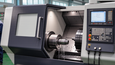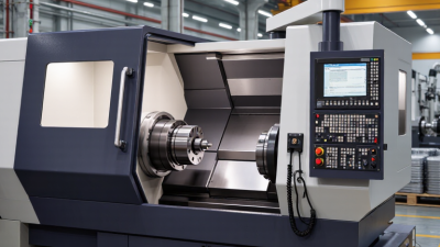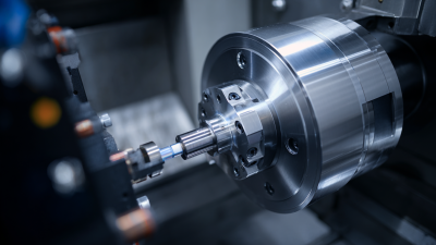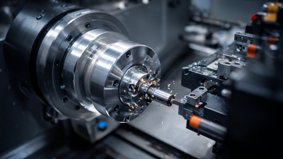
A cnc turning center is more than a computer-controlled lathe. It is a coordinated machining system designed to rotate a workpiece while cutting tools shape its surface. Depending on the model, it may also drill, thread, bore, mill, and perform live-tool operations. A steel bar enters the chuck, the spindle accelerates, and programmed tools remove material in measured passes. Coolant flows across the cutting zone. Chips collect below the work area.
Machining educator Kip Hanson offers a practical reminder: “The machine follows the program, but the programmer controls the result.” That idea explains why understanding the process matters. A modern cnc turning center can deliver tight tolerances and repeatable production, but it cannot correct poor workholding, damaged inserts, or an inaccurate tool offset. The machine is powerful. It is not magic.
This guide will explain the main components, operating sequence, control system, tooling, and common applications of a cnc turning center. It will also show how raw stock becomes a finished component through setup, programming, cutting, inspection, and adjustment. Small details matter. A loose chuck, an incorrect diameter value, or excessive cutting speed can leave visible marks on the part. Some explanations may simplify real shop-floor decisions, because material grades, machine brands, and production goals vary widely. That limitation deserves attention. Reliable results come from combining machine capability with verified programs, suitable tooling, careful measurement, and experienced judgment.
What Is a CNC Turning Center?
A CNC turning center is a computer-controlled machine that shapes rotating workpieces with cutting tools. The material usually sits in a chuck, while the spindle turns it at a programmed speed. A tool then moves along precise X and Z axes, removing metal to create diameters, shoulders, grooves, threads, or tapers. The machine may process steel, aluminum, brass, plastics, and other machinable materials.
It is more versatile than a basic engine lathe. Many turning centers include powered tooling, automatic tool changes, drilling functions, and milling capability. With these features, one setup can produce a part with holes, keyways, and threaded sections. That reduces handling and improves consistency. Still, setup quality matters greatly. A poorly tightened chuck or incorrect tool offset can ruin an otherwise accurate program.
The process begins with a digital drawing and a machining program. An operator loads the material, selects tools, enters work offsets, and checks the cutting conditions. The control system then directs every movement. Coolant may flow over the cutting edge, carrying away heat and chips. During production, the operator measures critical features with calipers, micrometers, or gauges. The first test cut can reveal problems that software misses. Real machining is not perfectly predictable. Tool wear, material variation, vibration, and imperfect alignment still demand experienced judgment.
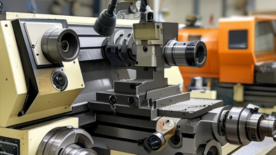
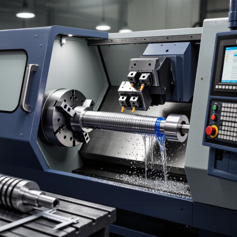
A CNC turning center is a computer-controlled machine for producing round or cylindrical components. Its main parts work as one system. The spindle rotates the workpiece inside a chuck or collet. The turret holds several cutting tools and moves them along controlled axes. The bed supports the machine, while guideways keep tool movement stable. A tailstock may support long workpieces. The control unit converts programmed instructions into precise movement.
Tips: Inspect the chuck jaws before setup. Remove chips from contact surfaces. Even a small chip can affect alignment. Check tool offsets with a verified measuring method. Keep cutting fluid at the correct level, and watch for unusual vibration.
During operation, the spindle turns the material while a selected tool removes controlled layers. The turret changes tools when the program requires drilling, facing, grooving, or threading. Encoders help monitor position, but they do not correct every setup mistake.
A sharp tool can still produce a poor finish if the workpiece is clamped badly. Measurement remains essential. In my experience, the most overlooked parts are often the chuck, tool holder, and coolant path. They seem simple. They are not. Operators should review tool wear, surface finish, and dimensional results during production. CNC automation improves repeatability, but careful judgment still protects accuracy.
A CNC turning center processes a workpiece by rotating it against controlled cutting tools. The operator secures the material in a chuck and checks its alignment carefully. A digital program then defines spindle speed, feed rate, tool movement, and cutting depth. Before production, the operator loads tool offsets and verifies the work coordinate. A small error here can affect every dimension.
The machine may begin by facing the raw end, creating a flat reference surface. It then performs turning passes to reduce the outside diameter. Boring tools enlarge or finish internal holes with measured precision. Grooving and threading tools create narrow channels or accurate screw profiles. Coolant carries heat and chips away from the cutting zone. The spindle must maintain stable speed, especially when the diameter changes.
During machining, the operator watches for vibration, unusual sound, and poor chip formation. These details often reveal problems before a measurement confirms them. After a pass, calipers or a micrometer check the critical dimensions. I have found that a perfect simulation cannot replace this physical inspection. Tool wear, material hardness, and clamping pressure can change the result. Sometimes, a slower feed produces a better surface, even when the program appears efficient. That trade-off requires judgment, not blind reliance on automation.
| Process Stage | Machine Action | Workpiece and Tool | Control or Setup Considerations | Typical Result |
|---|---|---|---|---|
| 1. Prepare the machining plan | The operator or programmer defines the sequence of turning and, where equipped, milling or drilling operations. | The plan is based on the part drawing, material, required features, and specified tolerances. | Tool paths, cutting conditions, work offsets, and the machine’s available axes and tooling are checked. | A CNC program and setup plan for producing the part. |
| 2. Load and clamp the stock | The bar or individual blank is positioned and secured in a chuck, collet, or other suitable workholding device. | The workpiece is typically cylindrical stock, although other shapes may be machined with appropriate workholding. | Clamping force and stock projection must suit the material, part geometry, and machining forces. | The workpiece is held securely for controlled rotation. |
| 3. Set the work and tools | The operator establishes the work coordinate system and confirms each tool’s position and geometry. | Cutting tools are mounted in a turret or tool system; tool types may include turning, grooving, threading, and boring tools. | Tool offsets, insert condition, clearance, and the programmed reference point are verified. | The machine can position tools accurately relative to the workpiece. |
| 4. Start spindle rotation | The CNC commands the spindle to rotate the clamped workpiece at the programmed speed. | The cutting tool is brought into contact with the rotating stock as required by the operation. | Spindle speed may be fixed or controlled using constant surface speed, depending on the program and machine settings. | Rotational motion supplies the primary cutting motion for turning. |
| 5. Remove material by turning | The machine moves a cutting tool along programmed axes, commonly the X and Z axes, to cut the rotating workpiece. | Facing, straight turning, taper turning, grooving, and other operations can be performed with suitable tools and programming. | Feed rate, depth of cut, tool path, and cutting conditions are selected for the material and operation. | The outside diameter, end face, shoulders, or grooves are machined to the programmed geometry. |
| 6. Machine holes, threads, or features | The machine can drill, bore, or cut threads using appropriate tools and coordinated movement. | Axial holes are commonly made with drills or boring tools; threading tools form internal or external threads. | Live tooling, a C-axis, or a Y-axis may enable off-center holes or milling features when the turning center is equipped for them. | Additional part features are produced without necessarily moving the workpiece to another machine. |
| 7. Transfer or complete the part | Some turning centers can pass a part to a sub-spindle for machining on the opposite end; others complete the part in one spindle setup. | A sub-spindle, bar feeder, or part catcher is optional and depends on machine configuration. | Transfer timing, workholding, and remaining stock length must be coordinated by the program. | Both ends may be machined in one cycle when the machine and setup support it. |
| 8. Inspect and unload | The finished part is released or collected, then checked against the drawing and quality requirements. | Measurements may include diameters, lengths, bore sizes, thread dimensions, and surface condition. | Inspection tools and sampling frequency depend on the part specification and production process. | A verified part ready for the next operation or use. |
A CNC turning center holds a workpiece in a chuck and rotates it around a fixed spindle axis. Cutting tools move along programmed paths to remove material accurately. Operators commonly use it for turning, where a tool reduces the outside diameter. Facing creates a flat end surface. These cuts can produce stepped shafts, tapers, shoulders, and precise cylindrical features.
The machine can also perform boring, drilling, reaming, and threading. Boring enlarges an existing hole with controlled accuracy. Drilling creates new holes along the spindle centerline. Reaming improves hole size and surface finish. Threading tools form internal or external screw threads, while grooving cuts narrow channels for seals or retaining rings. Parting tools separate the finished component from its remaining bar stock.
Many turning centers include driven tools for milling, tapping, and cross-hole drilling. This capability reduces extra setups and keeps feature positions related to one datum. A typical component may receive a milled flat, a radial hole, and a threaded end in one cycle. However, every operation depends on correct workholding, tool offsets, cutting speed, and chip control. A small offset error can leave a shoulder too large or damage a finished thread. In practice, the process is less tidy than a program screen suggests. Skilled operators still check the first part, measure critical diameters, and adjust cautiously. Surface finish may also change when a tool begins to wear.
Typical operation availability on a 2-axis CNC turning center
A CNC turning center rotates the workpiece while cutting tools shape it. Turning, facing, grooving, threading, drilling, and boring are commonly performed on a standard 2-axis setup. Cross-drilling and milling typically require live tooling or additional axes. Capabilities vary by machine configuration.
A CNC turning center rotates a workpiece against cutting tools, producing features such as shafts, bores, and threads. Its accuracy depends on more than the programmed coordinates. Heat from the spindle, cutting process, and workshop can shift the tool-to-workpiece relationship. A review in CIRP Annals by Mayr and colleagues reports that thermal effects may account for 40–70% of machine-tool errors in some conditions. The exact share varies with machine design and operating state.
Tool condition and setup matter just as much. A worn insert can leave a rough surface or push a slender part off-center; an uneven chuck grip can cause runout. Productivity also reflects tool-change time, workholding, chip removal, and how consistently operators load parts. Faster cutting is not always faster production. Excessive speed may shorten tool life and trigger more stops. Even coolant temperature can make a small difference.
Tips: Warm up the spindle before precision work, then check a test cut against a calibrated gauge. Track insert wear and repeatability across several parts, not just one. ISO 230-2 provides methods for measuring and evaluating a machine’s axis-positioning accuracy and repeatability. A shop can use those checks to spot drift early, though inspection routines still need regular review.