What Are CNC Turning Parts?
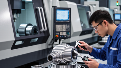
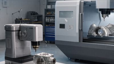
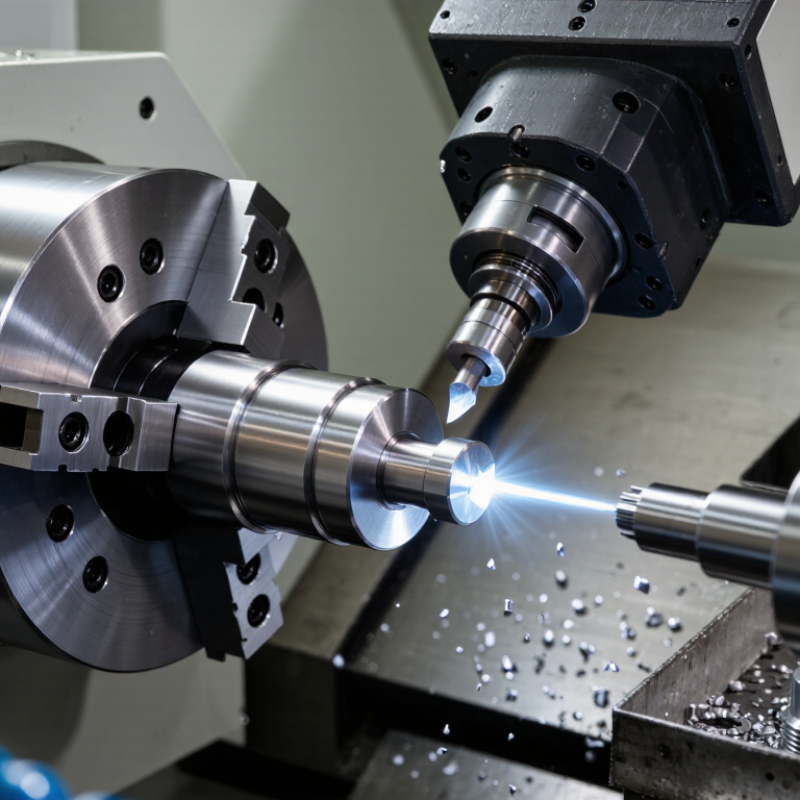
CNC turning parts are components shaped by rotating a workpiece against a cutting tool. The process can produce shafts, bushings, pins, threaded fittings, and other round features. A bar of metal spins in the chuck while a programmed tool removes material. Coolant runs over the cutting zone. Chips curl away. The final dimensions depend on the machine setup, tool condition, material, and inspection.
Manufacturing researcher Dr. David Dornfeld’s work offers a useful expert perspective: machining decisions should be judged by more than the cut itself. In practice, that means considering accuracy, surface finish, repeatability, and material use. A small drawing detail can change the setup. A tight tolerance may require extra passes or closer measurement. Even a clean-looking part can miss its specification.
That definition is tidy. Shop floors are not. A worn insert, an unexpected burr, or a poorly supported workpiece can affect the result. Understanding cnc turning parts means looking beyond the machine’s programmed path. This guide explains how turning works, which features it suits, and what affects part quality. It also considers material choice, tolerances, finishes, and common design decisions. Those details help engineers and buyers ask better questions before production begins.
What Defines a CNC Turning Part? Rotational Geometry and Lathe Axes
A CNC turning part is shaped while its stock rotates around a spindle axis. Its geometry usually follows that axis, creating cylinders, cones, steps, or circular grooves. A turned shaft, for example, may have a narrow neck, a larger bearing seat, and a threaded end. The key feature is rotational symmetry, though some parts include flats or cross-holes made with additional machine motions.
On a typical CNC lathe, the Z axis runs parallel to the spindle, while the X axis moves the cutting tool toward or away from the centerline. Z movement controls where features sit along the part; X movement sets their radial depth and diameter. Small errors matter. A slight offset can cause runout, uneven wall thickness, or a poor fit in an assembly. Short cuts help.
A part does not become a turning part simply because it was made on a lathe. Its shape and the way the cutting tool reaches that shape both matter. Designers should specify critical diameters, shoulders, and concentricity clearly. Yet not every surface needs tight tolerances; over-specifying them can add time without improving function. That judgment takes care.
What Defines a CNC Turning Part?
A turned part is defined by its rotational geometry: its diameter changes along the spindle axis. This example shows the profile of a stepped shaft.
Example dimensions: the shaft is 100 mm long, with 40 mm, 30 mm, and 20 mm diameter sections. On a lathe, Z runs along the spindle axis, while X controls the tool’s radial position; X is commonly specified using diameter values.
How CNC Turning Works: X–Z Toolpaths, Workholding, and Material Removal
What Are CNC Turning Parts?
CNC turning parts are components shaped as a rotating workpiece meets a cutting tool. The spindle turns the stock, while the tool follows programmed X–Z movements. X controls motion across the part’s radius; Z tracks its length. Together, these axes create shoulders, grooves, tapers, and straight diameters. Grand View Research estimated the global CNC machine market at USD 83.99 billion in 2023. Its report projected 5.3% annual growth through 2030, reflecting broad demand for automated machining.
Workholding sets the foundation. A chuck grips round stock, and suitable jaw pressure helps limit slippage without distorting thin walls. Before cutting, operators check alignment and runout; even a small error can leave uneven diameters. The tool then removes material in passes, with feed rate, depth of cut, and insert geometry shaping the finish. A roughing pass clears stock quickly. A lighter finishing pass refines the surface. But a shiny finish does not always mean the part meets tolerance. That detail is easy to overlook.
Tips: Keep the tool close to the chuck when possible, and verify the first part’s dimensions with a micrometer. Listen for chatter. If it appears, review tool reach, workholding, and cutting conditions before continuing. X–Z programming is simple to picture, but real setups can still surprise you.
Which Materials Are Turned? Aluminum, Steel, Brass, and Engineering Plastics
CNC turning parts are made by rotating a workpiece against a cutting tool, but the material shapes the result. Aluminum is light and cuts quickly; thin walls, however, can distort under clamping pressure. The U.S. Geological Survey’s Mineral Commodity Summaries 2024 estimates 70 million tonnes of primary aluminum production worldwide in 2023. Steel offers greater strength and wear resistance, though it generally needs more cutting force and heat control. World Steel Association data put 2023 crude steel production at 1,888.2 million tonnes. Brass is often chosen for fittings and small precision parts because it machines cleanly and resists corrosion. Still, alloy choice matters: “brass” covers grades with different cutting behavior.
Engineering plastics such as acetal, nylon, and PEEK suit lightweight parts that need electrical insulation or reduced friction. PlasticsEurope’s Plastics—The Facts 2024 reports 413.8 million tonnes of plastics production in 2023, across many types, not just engineering grades. That distinction matters. Plastic parts can soften, flex, or change size as heat builds during cutting. Nylon may also absorb moisture, affecting dimensions after machining. A useful design check is to compare the part’s operating temperature, load, and tolerance with the material data sheet. There is no perfect default. A test cut can expose warping or burrs that a drawing will not show.
How Are Turned Parts Specified? ±0.01 mm Capability and ISO 286 Fits
What Are CNC Turning Parts? How Are Turned Parts Specified? ±0.01 mm Capability and ISO 286 Fits
CNC turning parts are made by rotating a workpiece against a cutting tool, producing features such as shafts, bushings, and threads. A drawing should state the nominal diameter and its upper and lower limits, rather than relying on “precision” alone. A ±0.01 mm tolerance may be achievable for some turned features, but it is not guaranteed across every material, diameter, or production setup. Machine condition, part length, and temperature can affect the result. That is not guaranteed.
ISO 286 fit designations, such as H7/g6, define standardized tolerance zones for mating holes and shafts. They help indicate whether an assembly should have clearance, transition, or interference. Specify the fit on the relevant diameter and identify any important datum or inspection method. Surface finish matters too: a diameter can meet its size limits yet still perform poorly if the mating surface is too rough. Small details matter. It is easy to overlook how inspection temperature or measurement pressure can influence close readings, so confirm the inspection approach with the supplier.
Tips: State the nominal size, fit class, and critical surface finish on the drawing. Measure the actual part. For tight tolerances, agree on inspection equipment and sampling before production begins.