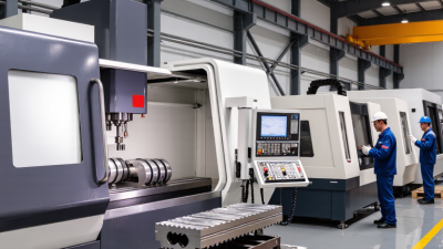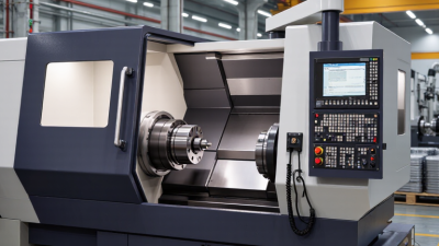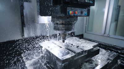
Choosing a vmc machine is not about buying the biggest spindle or the most impressive control. It is about matching machine capacity to real parts, materials, tolerances, and production volume. A compact aluminum component may need fast tool changes and high spindle speed. A heavy steel housing may demand rigidity, torque, and dependable chip removal. The right choice starts with the work on your shop floor.
VMC applications specialist Alex Morgan offers a practical rule: “Choose the machine around the hardest part you must make repeatedly, not the easiest part you make today.” That advice keeps selection grounded. Before comparing models, list your largest workpiece, typical fixture height, tool lengths, and required tolerances. Check the X, Y, and Z travels against the complete setup, not just the bare part. A table can look generous until a vise, rotary axis, and tall fixture take up space.
Then examine spindle speed, taper, tool capacity, control features, and service support. Ask for a cutting demonstration using material and tooling similar to yours. Watch for vibration, chip buildup, and access for maintenance. Those details matter. A brochure rarely shows a crowded tool-change area or awkward chip cleanup. Be honest about future demand, too; forecasts can be wrong. A machine with useful capacity and reliable local support may outperform a feature-heavy model that exceeds your process needs. This guide explains how to compare those factors and choose a vmc machine with fewer costly surprises.
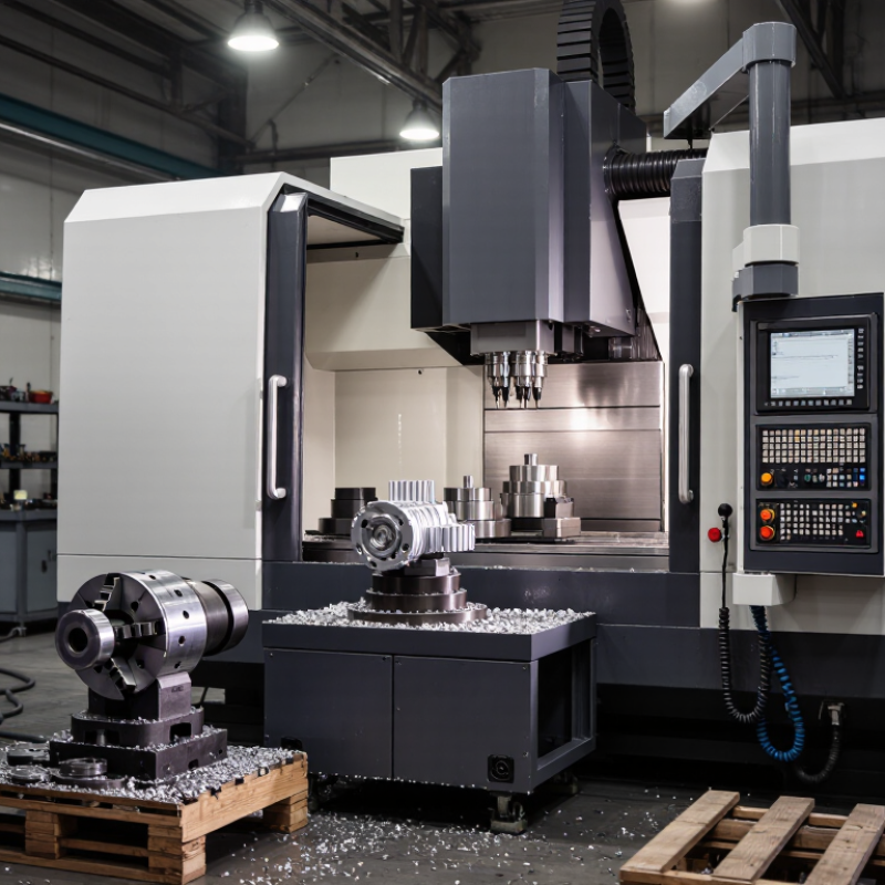
Define the work before comparing machine specifications. List the materials, part dimensions, tolerances, and features you actually cut. A 600 mm aluminum housing with shallow pockets needs different capacity from a steel plate with deep cavities. Note the largest tool, fixture, and workpiece together; usable table space is not the same as practical machining space. Record required spindle speed, torque, and tool capacity from your cutting plans, not from a sales brochure. Include realistic tolerance targets. A tight tolerance across a long part may require more attention to temperature and setup than the drawing suggests. Details matter.
Set production goals using parts per shift, annual volume, and expected changeovers. Estimate cycle time with tool changes, probing, loading, and inspection included. Then check whether the machine can meet demand without relying on constant overtime. The Deloitte and Manufacturing Institute 2024 study estimates that 1.9 million U.S. manufacturing jobs could go unfilled by 2033. That makes operator availability a useful planning constraint, not just a staffing concern. Consider whether one operator can safely tend multiple machines, and whether automation suits your part mix. A spreadsheet can still miss awkward setups. Review actual jobs with machinists, and challenge optimistic cycle-time estimates before choosing a machine.
How to Choose the Right VMC Machine
Compare VMC Types, Work Envelopes, and Axis Configurations
A vertical machining center’s work envelope is more than its X, Y, and Z travel. Check the usable table area, spindle-to-table distance, tool length, and door opening against your largest real part. A 600 mm travel rating can still feel tight when a fixture, vise, and long cutter occupy the space. Measure the complete setup, not just the raw workpiece. That detail is easy to miss.
A compact C-frame VMC suits smaller parts and limited floor space. A larger-travel machine handles longer components, while a double-column design can support broad, heavy work. Three-axis machines cover many prismatic parts; a fourth axis adds rotary access, and five-axis configurations can reach multiple faces with fewer setups. More axes also mean added programming and fixture demands. They are not automatically better.
Automation makes access worth checking. The International Federation of Robotics’ World Robotics 2024 report counted 4,281,585 industrial robots operating worldwide in 2023. That figure is not a VMC purchasing forecast, but it highlights why door clearance, pallet access, and chip evacuation matter when planning machine tending. I would still verify those details on the shop floor. Drawings rarely show every awkward clamp or cable. Then compare the supplier’s stated envelope with your actual setup, including tool changes and part loading.
| VMC type | Axis configuration | Typical linear work envelope (X × Y × Z) | Typical workholding / rotary capacity | Best suited for | Key selection consideration |
|---|---|---|---|---|---|
| Compact 3-axis VMC | X, Y, Z; fixed worktable | 400–600 × 300–400 × 300–500 mm (15.7–23.6 × 11.8–15.7 × 11.8–19.7 in) |
Typically a small fixed table; capacity varies by model | Small components, prototypes, toolroom work, and limited-floor-space shops | Check vise, fixture, and tool clearance—not just the part’s dimensions. |
| Standard 3-axis VMC | X, Y, Z; fixed worktable | 800–1,000 × 500–600 × 500–600 mm (31.5–39.4 × 19.7–23.6 × 19.7–23.6 in) |
Often accommodates one or more vises; table size and load rating are model-specific | General-purpose milling, drilling, tapping, and production machining | Allow room for multiple setups, clamps, and safe tool approach. |
| Large 3-axis VMC | X, Y, Z; fixed worktable | 1,200–1,600 × 600–800 × 600–800 mm (47.2–63.0 × 23.6–31.5 × 23.6–31.5 in) |
Large table; permissible workpiece weight depends on table and machine specifications | Large plates, molds, fixtures, and parts requiring long-axis machining | Verify table load, spindle reach, machine footprint, and installation requirements. |
| 4-axis VMC | X, Y, Z plus a rotary axis, usually A-axis rotation around X | Linear travel is commonly similar to a compact or standard 3-axis VMC; rotary setups reduce usable clearance. | Rotary table or indexer commonly about 200–400 mm (7.9–15.7 in) in diameter; varies widely | Parts needing machining on multiple sides or around a cylindrical axis | Check rotary diameter, center height, torque, payload, and collision clearance. |
| 5-axis trunnion VMC | X, Y, Z plus two rotary axes, commonly A and C | Often compact-to-standard linear travels; the trunnion and tilted workpiece limit usable part size. | Trunnion/table size is model-specific; usable workpiece diameter is less than the table’s nominal capacity. | Complex parts, multi-sided machining, and simultaneous 5-axis contouring | Assess part size at full tilt, rotary limits, fixture height, and tool-to-part reach. |
| 5-axis swivel-head VMC | X, Y, Z plus two rotary axes in the spindle head, often B and C | Linear travel varies by machine; head orientation and tool length affect reachable work area. | Usually a fixed table; workholding capacity depends on table dimensions and load rating | Larger or heavier parts that benefit from angled access and fewer repositioning operations | Check head tilt range, spindle-nose clearance, tool length, and angular accuracy. |
Note: Dimensions are broad, indicative ranges for common VMC classes, not guaranteed specifications or industry standards. Actual travels, rotary limits, table size, load capacity, and usable work envelope vary by machine design, options, workholding, and tool setup. Confirm the manufacturer’s detailed specifications and collision or simulation data before selecting a machine.
How to Choose the Right VMC Machine
Choosing a vertical machining center starts with the parts you make, not the largest spindle number on a specification sheet. Match spindle speed, torque, and power to your materials and cutters. Aluminum often benefits from higher speed; steel may need steady torque at lower RPM. Check the continuous rating, not just peak power, and ask how performance changes during long cuts. Small details matter. A short trial cut can reveal vibration that a table of specifications cannot.
Evaluate the control through your actual workflow: setup screens, probing routines, program transfer, and recovery after an interruption. Ask operators to run a familiar job. A clear interface can reduce setup errors, though training still matters. Tool capacity should reflect your real job mix, tool lengths, and change frequency. Check holder compatibility, magazine access, and clearance around fixtures.
Separate positioning accuracy from repeatability, and request the test conditions and measurement method behind each figure. For close-tolerance work, inspect a representative part after the machine reaches operating temperature. Then test it. Thermal drift, workholding, and tool wear can affect results too. I would leave room for doubt: one impressive sample does not prove consistent performance. Compare documented results with your own acceptance criteria.
How to Choose the Right VMC Machine
Assess Installation Needs, Operating Costs, and Supplier Support
Before comparing machine prices, check the floor, power supply, and access route. A VMC may fit on paper but fail at the doorway, or require costly electrical upgrades. Measure twice. Confirm foundation requirements, coolant handling, chip removal, and space for operators to load parts safely. Ask the supplier for installation drawings and a written commissioning plan, not just a delivery date. These details can prevent avoidable delays, though actual site conditions still need a qualified review.
Operating cost includes energy, tooling, maintenance, and lost production. The U.S. Department of Energy’s 2002 motor-systems assessment estimated that motor-driven systems used about 68% of manufacturing electricity. That figure covers the wider sector, not an individual VMC, and it is old; use it as context, then request machine-specific consumption data. Deloitte’s 2023 Smart Manufacturing Survey found that 86% of surveyed manufacturing executives expected smart manufacturing solutions to drive competitiveness within five years. Connectivity may help, but only if your staff can use it. Support matters. Ask about technician response times, spare-part availability, operator training, and software updates. Get service terms in writing. I would also ask for references from facilities with similar materials and shift patterns; one detail often overlooked is whether support remains available after installation week.
How to Choose the Right VMC Machine
Validate Your Choice Through Testing and Future Capacity Planning
A VMC’s quoted cycle time is only a starting point. Run a representative part through the full process: setup, tool changes, probing, cutting, and inspection. Use the material and tolerances your shop actually handles. Record cycle time, dimensional results, tool wear, and any rework. Small details matter. A warm spindle or awkward fixture can change the result. Ask for a repeat run, too; one clean part proves little.
Then compare demonstrated output with realistic demand. Include shifts, setup hours, maintenance, and operator availability—not just the machine’s advertised speed. The Federal Reserve’s G.17 report showed U.S. manufacturing capacity utilization at 77.6% in November 2023, a reminder that national averages cannot define a single shop’s workload. Build your own forecast from order history and likely part mix. The 2024 workforce study by Deloitte and the Manufacturing Institute projected that 1.9 million manufacturing jobs could go unfilled by 2033. That makes ease of setup and training worth testing alongside throughput. I would leave a buffer; forecasts can be wrong. Have operators run the trial, and note where they hesitate. A spreadsheet may miss that.
Example planning scenario: estimated parts per 8-hour shift at 85% planned availability. Replace these sample figures with results from your own acceptance tests and demand forecast.
A suitable machine should meet current demand and provide enough tested capacity for expected growth. Validate cycle time, part quality, and availability using representative production parts before making a final selection.